
NCRP-151: Linac Vault Shielding
Overview
NCRP-151 provides the standard formalism used in the United States to determine shielding requirements for megavoltage photon and electron beam sources. Shielding requirements are based on the intended use of the shielded area, the expected occupancy of the area, the fraction of time the beam will be directed at the barrier, and the total expected dose delivered to within the vault in a given week.
NCRP-151 Terminology
Controlled Area: Limited access areas where the occupational exposure of personnel to radiation is under supervision of a radiation protection program. These include treatment rooms, control areas and other working areas for radiation workers where non-monitored persons are not able to enter.
High Energy Accelerator: Any accelerator delivering a maximum photon energy greater than 10MV.
Low Energy Accelerator: Any accelerator delivering a maximum photon energy of 10MV or less.
Primary Barrier: A wall, ceiling, floor, or other structure that will directly intercept the primary radiation beam.
Secondary Barrier: A wall, ceiling, floor, or other structure that will not intercept the primary beam but will receive radiation scattered by interactions within the patient or other object including accelerator leakage radiation.
Uncontrolled Area: All areas not considered controlled areas are considered uncontrolled areas.
NCRP-151 Assumptions
NCRP-151 makes several conservative assumptions designed to produce safe vault designs at reasonable cost. The following are examples of conservative assumptions:
- Neglects patient attenuation (30%)
- Assumes beam takes the shortest path through the barrier. (i.e. That the beam is incident normal to the plane of the barrier)
- Head leakage is assumed to be the maximum allowed by IEC (0.1%)
- Occupancy factors are conservatively high
- Unusual procedures are given a safety multiplication factor (e.g. assume 1.5 times dose of measurement for TBI)
- Two-source-rule
Typical Shielding Requirements
| Room Type | Typical Shielding |
|---|---|
| High Energy Linear Accelerator Primary Barrier |
|
| High Energy Linear Accelerator Secondary Barrier |
|
| High Energy Linear Accelerator Door |
|
| Ir-192 HDR Suite |
|
| PET/CT Room |
|
| CT Room |
|
| Radiographic Suite |
|
Primary and Secondary Barrier Calculations
Transmission Factor Calculation (B)
Definition: Transmission factor, B, is the maximum allowable transmission which will allow the barrier to achieve its shielding design goals (P).
Transmission factor calculation is based on the treatment machine workload (W), use factor (U), and occupancy factor (T) as well as the distance beyond the barrier (d).
Primary Barrier Transmission Factor (Bpri)
Primary barrier transmission factor may be calculated as:
![]()
Because primary barriers experience fluences significantly higher than the expected fluence from patient scatter or head leakage, these factors are ignored for primary barriers.
Key Point: The minimum distance beyond the barrier is taken to be 0.3m as it is not expected that persons will stand directly against the wall.

Laminated (multi-material) Barriers
Laminated primary barriers typically consist of a layer of steel or lead encased within concrete. While this shielding solution is more expensive than concrete barriers, laminated barriers are used in some vaults as a way to save space.
Total transmission of laminated barriers can be calculated as the product of the total transmission of each component.
e.g. A barrier made of concrete, lead, and steel would have a total transmission of:
![]()
Secondary Barriers
Secondary barriers must shield both patient scatter photons and head leakage photons. Because the intensity and spectrum of each of these components will vary significantly with treatment type, they are handled separately.
Head Leakage Transmission Factor (BL)
![]()
Note that the factor of 0.001 is used as the maximum allowable head leakage is 0.1%.
Patient Scatter Transmission Factor (Bps)
![]()
a is fraction of the primary beam absorbed dose that scatters from the patient at a particular angle. This can vary by two orders of magnitude depending on the angle of scatter.
The subscripts sca and sec denote distance from source-to-scatterer and distance from scatterer-to-protected point respectively.
Scatter Fraction (a)
| Angle (degrees) | 6MV | 10MV | 18MV | 24MV |
|---|---|---|---|---|
| 10 | 1.04x10⁻² | 1.66x10⁻² | 1.42x10⁻² | 1.78x10⁻² |
| 45 | 1.39x10⁻³ | 1.35x10⁻³ | 8.64x10⁻³ | 8.30x10⁻³ |
| 90 | 4.26x10⁻⁴ | 3.81x10⁻⁴ | 1.89x10⁻⁴ | 1.74x10⁻⁴ |
| 135 | 3.00x10⁻⁴ | 3.02x10⁻⁴ | 1.24x10⁻⁴ | 1.20x10⁻⁴ |
Required Primary and Secondary Barrier Thickness
The minimum required tenth value layers (TVLs) of shielding, can be computed from the transmission factor as:
![]()
For primary barriers, B = BPri given above.
Secondary barriers must use the two-source rule to determine the barrier thickness. To apply the two source rule, barrier thickness should be calculated using both Bps and BL separately. The required shielding thicknesses are compared and, if the thicknesses differ by more than 1TVL, the larger of the two may values may be used. If both thicknesses are approximately equal, the larger thickness plus 1 additional HVL should be used.
Thickness of barrier can be found from TVLs as in the below equation where TVL1 is the first tenth-value-layer and TVLe is the equilibrium tenth-value-layer.
![]()
Note: TVL1 is not equal to TVLe because of spectral changes in the radiation as a function of depth.
Two-Source Rule
The Two-Source Rule treats the patient scatter and leakage components of secondary radiation as distinct sources. If the patient scatter and leakage transmission factors are approximately equal, shielding thickness may be taken as the larger of the two barrier thicknesses plus 1 HVL. If the thickness of each source differs by 1 TVL or more, the larger barrier thickness may be used. This may also be applied to different beam energies.
Workload (W)
Definition: Workload is the time integral of the absorbed-dose rate, determined at depth of maximum absorbed dose, 1m from the source.
![]()
Units: W is typically specified over one week making the units Gy/week.
Determining Workload: A workload should be determined for each accelerator energy. The best method is to find workload data from the clinic in question or from nearby clinics with similar patient populations. If no real life data is available, NCRP suggestions may be used.
- NCRP-151 suggested workloads:
- 1,000Gy/week for low energy accelerators (first sited in NCRP-49)
- 500Gy/week for high energy accelerators (first sited in NCRP-51)
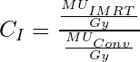
Workload of IMRT and Special Procedures
IMRT/SRS/SRT
IMRT, SRS and SBRT deliveries often use many small field sizes to achieve a highly conformal dose distribution. This means that more monitor units (MU) will be required per unit of prescription dose. This can significantly impact the head leakage calculations. Therefore, a leakage workload (WL) is used.
WConv is the workload as defined above only taking conventional treatments into account.
WIMRT takes into account the increased MU per Gy for non-conventional treatments through a factor CI.
![]()
Quality Assurance
Quality assurance deliveries (i.e. machine and patient specific QA) must also be included in workload. If many patient specific QA deliveries are IMRT, the CI factor must also be used.
TBI/Special Procedures
Because workload is defined at isocenter, treatments performed at extended SSD (e.g. TBI) must be accounted for using their dose at isocenter rather than prescription dose.
Key Point: Because workload is defined at isocenter, treatments performed at extended SSD (e.g. TBI) must be accounted for using their dose at isocenter rather than prescription dose.
Use Factor (U)
Definition: Use factor is the fraction of the workload at which the treatment beam is directed at a given primary barrier.
Determining Use Factor: NCRP provides the following table with expected use factors for a high energy linear accelerator. Importantly, use factors may differ significantly from these reference values. For example, TBI may be performed only at a single gantry angle and will influence use factors for the impacted wall.
Data from NCRP 151 table 3.1
| Angle (90 degree interval) | U(%) |
|---|---|
| 0 degrees (down) | 31.0 |
| 90 and 270 degrees | 21.3 |
| 180 degrees (up) | 26.3 |
Secondary Barrier Use Factor
Key Point: Although NCRP-151 only defines a use factor for primary barriers, the report does reference a use factor of 1 for secondary barriers.
Occupancy Factor (T)
Definition: Occupancy factor is the average fraction of time that the maximally exposed individual is present in a given location while the beam is on.
Determining Occupancy Factor: Standard occupancy factors are provided in the table at right. Note that these are created assuming a 40 hour equipment use week. If the beam on time is greater than 40 hours, the occupancy factor is determined by the ratio of the average time the maximally exposed individual in an area will be present to the total average time the equipment is used. (e.g. A person present 40 hours/week near equipment that is operated 60 hours/week would have a use factor of (40/60)=0.67.)
Key Point: The location for occupancy factor is usually assumed to be 30cm beyond the barrier.
| Occupancy Factor (T) | Location |
|---|---|
| 1 | Full occupancy areas: Offices, Treatment planning areas, Control rooms |
| 1/2 | Adjacent treatment rooms, Patient exam rooms |
| 1/5 | Corridors, Employee lounges, Staff rest rooms |
| 1/8 | Treatment vault doors |
| 1/20 | Public rest rooms, Unattended vending and storage areas, Unattended waiting rooms, Closets |
| 1/40 | Outdoor areas with only passing traffic, Unattended parking lots, Unattended vehicle drop off areas, Stairways |
Shielding Design Goals (P)
Definition: Maximum acceptable levels of Dose Equivalent for a given location.
Units: mSv/year, mSv/week
Time Average Dose Rate (TADR)
Because measurements of transmission are typically taken as instantaneous dose rate, they cannot be directly used to determine the shielding adequacy. To resolve this problem, instantaneous dose rate (IDR) measurements are averaged over a week (Rw) or an hour (Rh).
![]()
D is the absorbed-dose output rate at 1m (Gy/hr)
![]()
Nmax is the maximum number of patients per hour.
Nw is the average number of patients per week.
| Area | Dose Equivalent |
|---|---|
| Controlled Areas | P < 5mSv/year P< 0.1mSv/week |
| Uncontrolled Areas | P < 1mSv/year P < 0.02mSv/week Rh < 0.02mSv/hour (NRC requirement) |
Neutron and Neutron Capture Photon Calculations
High energy linear accelerators produce photoneutrons in the treatment head, fixation equipment, and primary barriers. Neutron shielding requires considering both direct neutron dose and dose resulting from neutrons capture gamma photon emission.
Concrete Primary Barriers
Concrete has a high hydrogen content which is able to efficiently attenuate linac neutron production. Therefore, concrete primary barriers meeting the above photon shielding requirements will not require additional shielding to protect against neutron or neutron capture gamma ray dose.
Neutron Capture Gamma Energy
BPE = 0.48MeV
Hydrogen (concrete) = 2.2MeV
Laminated Primary Barriers
Total dose equivalent transmitted through a primary barrier is the sum of the neutron and photon dose equivalents.
Neutron Dose Equivalent
The following empirical formula is used to compute neutron dose equivalent for linear accelerators.
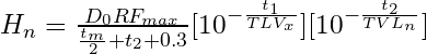
Hn = neutron dose equivalent per week (μSv/week)
D0 = X-ray absorbed dose per week at isocenter (cGy/week)
R = neutron production coefficient ( in neutron μSv per X-ray cGy per beam area in m2) (i.e. μSv/cGym2)
Fmax = maximum field area at isocenter (m2)
tm = metal slab thickness (m)
t1 = first concrete slab thickness (m)
t2 = second concrete slab thickness (m)
TVLx = tenth-value layer in concrete for X-ray beam (m)
TVLn = tenth-value layer in concrete for neutrons (m)
0.3 = distance from outer surface of the barrier to point of occupancy as defined in NCRP 151 (m)
Neutron Capture Gamma Dose Equivalent
For 15 and 18MV photon beams, it has been shown that the following equation gives a conservatively safe estimate of total photon dose equivalent (primary photon plus neutron capture gammas).
![]()
Htr = X-ray dose equivalent.
If Bpri is known Htr may be a calculated as:
![]()
Neutron Capture Gamma Energy
BPE = 0.48MeV
Hydrogen (concrete) = 2.2MeV
Structural Considerations
Primary Barrier Width
Primary barrier width is determined by projecting the maximum field size from the target (not from isocenter) to the primary barrier and adding 30cm on each side.
If the barrier protrudes into the room, the maximum field size should be taken at the plane of the inner portion of the secondary barrier. If the barrier extends out of the room, the barrier is calculated at the outer part of the primary barrier.
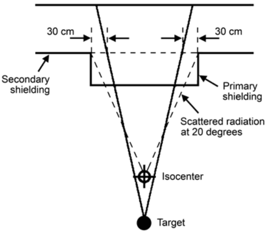

Key Point: Maximum field size will be the diagonal of the maximum collimator setting. The maximum field size of a 40 x 40 cm2 field is about 50cm at isocenter.
Door Design
High energy vault doors must be able to shield for high energy X-rays as well as neutrons and neutron capture gamma rays. Because of weight and volume concerns, doors usually use a laminated construction method.
Typical door construction consists of three layers:
- Inner layer of high z material (typically lead). In addition to attenuating the incident photons, this layer is also able to reduce the energy of fast neutrons making the BPE layer more effective.
- A middle layer of Borated Polyethylene (BPE) attenuates the thermal neutron flux. This layer, however, will produce neutron capture gamma rays.
- BPE Neutron TVL assumed to be 4.5cm
- BPE Neutron Capture Gamma Energy = 0.48MeV
- The attenuation cross-section of Boron is approximately 10,000 times that of hydrogen!
- The outer layer of high z material (typically lead) attenuated the neutron capture gamma rays produced in BPE.

Key Point: Hydrogen is a superior neutron attenuator than lead or tungsten because it has approximately the same mass as a neutron. Therefore, conservation of energy and momentum allows the hydrogen atom to absorb a maximum of the neutron’s energy.
Mazes
Many high energy vaults utilize a maze to reduce the size, weight, and complexity of the vault door.
Maze calculations require special attention as both the reflected and transmitted dose must be accounted for in the shielding design. Because of their complexity, the reader is encouraged to review the full NCRP-151 report.

Tenth-Value-Distance (TVD)
Tenth value distance (TVD) is the maze distance required to reduce photon and thermal neutron fluence by a factor of 10.
![]()
- For most mazes the TVD is approximately 4-5m.
- Thermal neutron fluence also reduces by a factor of approximately 3 for each leg of the maze.
Skyshine and Groundshine
Skyshine
Skyshine refers to radiation scattered off of the atmosphere back to the ground or surrounding buildings.
Skyshine can become an issue for treatment vaults with lightly shielded ceilings.
Groundshine
Groundshine refers to radiation scattered off of the ground below the vault back to the surface outside the vault.
Groundshine is sometimes a problem with vault designs that use earth as the floor shielding.

Navigation
Not a Member?
Sign up today to get access to hundreds of ABR style practice questions.