
Photon Dose Distributions
Photon Beam Basics
Photon Beam Quality (Energy Spectrum)
X-ray beam quality refers to the spectrum of energy present in a beam which greatly impacts its ability to penetrate a medium. Quality of an X-ray beam is dependent upon many factors including the whether the source is a decaying nuclide, which produces beams of characteristic energies, or the product of bremsstrahlung reaction which produces a polyenergetic beam. If the beam is produced by bremsstrahlung, factors including incident electron energy, target design, and collimation can greatly impact beam quality.
The ideal description of beam quality would be a complete histogram of the relative fluence of photons at every energy. In practice however, this information is not readily available. Therefore, several simplified means of describing beam quality are in used.
Half Value Layer
Half-value layer (HVL) describes beam quality by the thickness of a given material required to reduce the incident beam's fluence by 50%. Half-value layer is commonly used in describing the quality of kilovoltage photon beams using the HVL of aluminum (superficial beams) or copper (orthovoltage beams). HVL is not a practical description of megavoltage photon beams because of the mass of material required.
Photon beam energy levels
- Superficial: 10keV-100keV
- Orthovoltage: 100keV – 500keV
- Megavoltage: >1MeV
Megavoltage X-ray beam Quality
Megavoltage X-ray beam quality is usually measured by attenuation of water or synthetic water. One common approach uses the ratio of maximum dose to dose at a depth of 10cm. This approach is called the percent depth dose (%DD(10cm)) and is used in AAPM TG-51 as a measure of beam quality index. Another approach, called the nominal accelerating potential (NAP) or 10/20 ratio, compares the absorbed dose at a depth of 10cm in water to absorbed dose at a depth of 20cm in water using a common SSD (100cm).
Percent Depth Dose (%DD)
Percent depth dose (%DD) distributions give the dose, relative to maximum dose, as a function of depth. There are several key features of a %DD chart that should be noted.

Skin Sparing
MV photons do not reach maximum dose at the surface/skin but build-up to a maximum dose. This effect is referred to as skin sparing and is desirable for most photon treatments.
Depth of Maximum Dose (dmax)
The depth of maximum dose is closely connected to photon energy but also source-to-surface distance, field size and beam profile.
Dose Fall Off
Dose fall off is gradual for photon beams. The slope of the fall off decreases with increasing photon energy.
Factors Influencing %DD

Inverse Square Law
The intensity of a photon point source will fall off as a function of the inverse of the square of the distance from the source ![]() .
.
![]()
The inverse square law occurs because photons from an anisotropic point source propagate spherically outward. As they do, the density of photons decreases as the surface area of the sphere increases.
![]()

Key Point: %dd increases slightly as SSD increases
This is because the ratio of inverse square from depth-of-interest to dmax approaches unity (1) as distance increases.
Attenuation
Photon attenuation is the process by which photons interact with matter and deposit some or all of their energy. Attenuation is influenced both by the material the beam is passing through and by the energy of the beam.
Attenuation is often measured using an attenuation coefficient, μ, normalized to the density of a material, ρ, referred to as a mass attenuation coefficient. The units of mass attenuation coefficients are cm2/g.
There are several attenuation coefficients to be aware of:
- Mass Attenuation Coefficient

- The fraction of primary photons removed from the beam per unit distance over medium density.
- Mass Energy Transfer Coefficient
- The fraction of primary beam energy transferred to charged particles in the medium per unit distance over medium density.
- Mass energy transfer coefficient is related to KERMA (Kinetic Energy Released per unit MAss) as:
- Ψ is the photon energy fluence
![]()
- Mass Energy Absorption Coefficient
- The fraction of primary beam energy by the medium per unit distance over medium density.
- Dose is related to Mass Energy Absorption Coefficient as:
- Ψ is the photon energy fluence
![]()
Key Point: KERMA and Dose are related by the relationship between Mass Energy Transfer Coefficient (which relates to energy transferred to charged particles that travel some distance) and Mass Energy Absorption Coefficient (which relates to local energy deposition).
Poly-energetic beams
Modern linac-generated photon beams consist of a spectrum of energies up to the maximum energy. Because attenuation is higher for the lower photon energies, the average energy of the photon beam becomes higher at deeper depths. This process, known as beam hardening, causes the average beam attenuation to decrease with depth.
Buildup
Buildup occurs because much of the energy transferred from the photon beam is initially absorbed by electrons which travel some distance. This energy is eventually deposited as dose at a deeper depth within the phantom.
The buildup region ends when the amount of energy taken downstream by liberated electrons is equal to the energy deposited at that location by electrons liberated upstream. This condition is known as charged particle equilibrium (CPE).
Depth of maximum dose (dmax) is found at the shallowest point where charged particle equilibrium is established. Prior to this point, more energy is carried away by liberated electrons than is deposited locally by electrons liberated upstream. Beyond dmax, attenuation and inverse square law reduce the intensity of the primary photon beam with increasing distance.
Isodose Charts
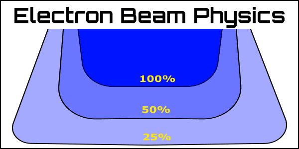
Isodose charts provide a 2D map of a dose distribution. Isodose charts are typically normalized to maximum dose but, especially in treatment planning, may be normalized to prescription dose.
Isodose charts illustrate several important aspects of MV photon dose distributions:
Central Axis
Dose is highest along the central axis of the beam.
Exception: For beams generated with a flattening filter there are often "horns" in the superficial isodose lines. The flattening filter overcompensates in this superficial region to produce a flatter dose distribution at treatment depths.
Field Edge
Dose near field edge falls off rapidly. This is caused both by geometric penumbra and also loss of lateral scatter equilibrium.

Flattened field "horns"
The horns found in shallow depths of flattened fields are caused by differential attenuation within the flattening filter. Horns are most pronounced for lower MV fields and larger field sizes where the lateral photon energy is much lower (softer) than along the central axis.
Factors Influencing Dose Distributions
Energy Spectrum
Energy: Impact on %DD
Increased photon energy increases depth of maximum dose (dmax) because electrons liberated by the primary beam are of higher average energy. This means that the electrons travel farther and require more depth to reach charge particle equilibrium.
Increased photon energy decreases the slope of the dose fall off. This effect follows directly from the reduction of photon attenuation with increased energies.
MV Energy Spectrum
Linear accelerators create beams using Bremsstrahlung interaction. This means that they have a spectrum of energy rather than a single energy. Beam hardening, therefore, causes the slope of %DD to decrease at increasing depth.

Key Point: Energy of photon beams produced by linear accelerators are designated by their peak energy and MV (e.g. 6MV.) MV is used to distinguish these poly-energetic beams from mono-energetic beams which may use MeV.
Important Depth Dose Numbers to Remember
All data referenced to 10cm by 10cm fields. Dose fall-off beyond dmax calculated as average to a depth of 20cm using data from Kahn's The physics of Radiation Therapy, 4th edition or clinical data. Attenuation uses TMR data listed and compares with commonly accepted "rule-of-thumb."
| Photon Energy (MV) | dmax (cm) | %DD at 10cm depth | TMR at 10cm depth | Dose Fall-off beyond dmax (%/cm) | Attenuation rate Calculated & (Rule-of-thumb) |
|---|---|---|---|---|---|
| Co-60 SSD/SAD = 80cm | 0.5 cm | 56% | 0.68 | 3.7%/cm | 3.4%/cm |
| 6MV | 1.5 cm | 67% | 0.77 | 3.3%/cm | 2.7%/cm (3%/cm) |
| 10MV | 2.5 cm | 73% | 0.84 | 3.1%/cm | 2.1%/cm (2.5%/cm) |
| 18MV | 3.2 cm | 80% | 0.91 | 2.8%/cm | 1.3%/cm (2%/cm) |
Energy: Impact on Scatter Angle

Higher energy photons will be scattered in a more forward direction than lower energy photons.
- This effect is the result of conservation of energy and momentum during elastic collisions.
- This effect is strongest for kV photons and has little impact on MV photons.
In the kV photon range, decreased energy causes the lower isodose lines to bulge out.

Beam Profile
Field Size
Percent depth dose increases with increasing field size.
Field size has the greatest impact on %DD for small fields.
Surface dose also increases with increased field size due to increased lateral scatter.
Equivalent Square Rule: A rectangular field has a %DD curve equivalent to a square field of the same Area to Perimeter ratio.
Although %DD curves are generally produced for square fields, many clinical fields are not square.
![]()
Key Point: Equivalent square is only valid for rectangular fields. Application to irregular fields will yield inaccurate results!
Field size designations
Geometric Field Size is defined as the projection of the primary collimator to the treatment difference. This is the field size defined by the light field.
Dosimetric/Physical Field Size is defined by the size of a given isodose line (typically 50%) at depth. This is often referred to as the full width at half maximum (FWHM).


Penumbra
A penumbra is the partially shaded region on the boarder of an open photon field and a block. Dose rapidly falls off in the penumbra region.
Geometric Penumbra
Geometric penumbra arises because the photon source has some finite size. As a result, the source is partially occluded near the field edge.
Geometric penumbra (GP) is dependent on source size (S), source-to-surface distance (SSD), depth (d), and source-to-collimator distance (SCD).
Geometric penumbra increases with:
-
- Increasing source size
- Increasing SSD
- Decreasing field size, especially fields similar to the source size
- Decreasing source to collimator distance
![]()
Transmission Penumbra
Transmission penumbra occurs as the result of incomplete attenuation of the beam at the edges of the collimator.
Transmission penumbra is dependent upon the construction of the collimator and, because of the changing collimator and beam angle, field size.
Physical penumbra
Typically defined as the lateral distance between the 80% and 20% isodose lines.
Physical penumbra includes the effects of geometric penumbra and transmission penumbra as well as a loss of CPE due to scattering near the field edges.

Key Point: Energy (in addition to collimator design, field size, and SAD) has an impact on penumbra. Lower energies tend to cause less transmission penumbra but have greater lateral scatter than higher energies. These competing effects yield the smallest physical penumbra at about 10MV in soft tissue.
Flatness and Symmetry
An unflattened MV photon beam will have its highest dose rate along the central axis of the beam. Dose rate falls off laterally resulting in a peaked isodose distribution.
Flattening Filters are cone-shaped pieces of metal commonly used to normalize the dose distribution laterally. These filters are designed to attenuate the central axis of the beam leaving a very uniform dose distribution at a given depth, usually 10cm. Shallower than this depth, the lateral region will have the highest dose rate which appear as "horns" on the dose distribution. Beyond 10cm depth, the dose distribution again becomes forward peaked.
Flatness
Flatness is defined in AAPM TG-45 as the ratio of the maximum to the minimum dose inside the central 80% of the field width at a given depth. Field width defined here as full width at half maximum (FWHM).
A flatness of +/-3% is acceptable.
![]()
Symmetry
Symmetry is defined in AAPM TG-45 as a maximum deviation of the left side dose from the right side dose of a beam over the central 80% of FWHM.
A symmetry value of +/-2% is acceptable.

Key Point: Because linac photons are emitted in a continuous spectrum of energies, flattening filters cause differential beam hardening. As a result, flattening filters only achieve flatness at a limited depth range, usually 10cm.
Source-to-Surface Distance (SSD)
Dose rate decreases with increased SSD
Due to the impact of the inverse square law.
%DD increases with increased SSD
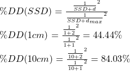
This is because percent depth dose is the ratio of dose-at-depth to dose at dmax. Ignoring attenuation, the dose difference at each of these points is determined by difference in inverse square law. This difference is greatest for short SSDs.
For example, take dmax = 1cm and d = 2cm. Evaluating at an SSD of 1cm and ignoring attenuation %DD = 44% while at an SSD of 10cm %DD = 84%.
Key Point: Converting %DD curves measured at one SSD to another SSD can be accomplished using the Mayneord F-factor.
Inhomogeneities
Inhomogeneities are regions of non-uniform electron density. These regions perturb the dose distribution and must be accurately modeled to determine local absorbed dose.
Electron Density
The Compton interaction is the dominant form of interaction between clinical photon beams and body tissues. Because the Compton interaction is the interaction of a photon with a single electron, knowledge of the electron density is important for determining beam attenuation.
For low Z atoms, such as those found in soft tissue, electron density is closely related to physical density. We can therefore convert CT number to physical density and use this for computing a dose distribution in the presence of non-uniform density.
Most elements in soft tissue have nearly the same Z/A ratio (0.5). Hydrogen is an important exception (Z/A=1).
The impact of pair production and photoelectric effect increases with increased atomic number. This becomes especially important for dose to bone.
Key Point: CTs are useful because the let us determine the number of electrons per unit volume.

Low Density (Air/Lung)
Lung tissue has a density of about 1/3 to 1/4 that of soft tissue. Because of this density difference, the interface of lung and soft tissue produces some of the strongest dose perturbations in the patient's body. Further, this perturbation has significant impact on the dose calculation accuracy for the lungs and targets within lungs.

Influence of low-density tissue inhomogeneities:
- Dose is reduced at the upstream tissue/lung interface.
- Within tissue, this is the result of loss of backscatter.
- Within the lung, dose is initially depressed but will build up to exceed dose in a homogeneous medium.
- The excess dose here is the result of decreased primary beam attenuation.
- Penumbra within the lung will be greater because of increased electron range.
- This effect is greatly increased for higher energy beams.
- At the exiting lung/tissue interface, dose will again be depressed and need to build-up.
- Beyond the low-density inhomogeneity, dose will be increased.
Key Point: Lung targets are usually treated with low MV photons because higher energies result in greater lung dose (increased scatter) and decreased target coverage (increased target buildup region).
High Density (Bone)
The impact of bone on a depth dose distribution arise both directly from the increased density of bone but also from the increased contributions of pair production and photoelectric effect caused by the higher atomic number constituents in bone.
Atomic numbers of bone constituents
Calcium: 20
Carbon: 6
Oxygen: 8

Influence of high-density tissue inhomogeneities:
- Dose directly upstream of tissue/bone interface increases.
- This is the result of increased backscatter.
- 5-10% increase for MV fields.
- Within bone, dose to bone decreases.
- This is the result of lower electron density due to presence of high Z elements within bone.
- For soft tissue embedded in bone, the dose will increase above dose in the absence of bone.
- Result of two effects work together to increase the number of secondary electrons and increase their rate of energy deposition.
- The mass attenuation coefficient of bone is greater than for soft tissue, this causes an increase in secondary electrons liberated by the photon beam.
- The stopping power ratio for soft tissue is greater at all energies because the electron density of soft tissue is greater than bone. This means that more of the electron energy is imparted to the soft tissue.
- Result of two effects work together to increase the number of secondary electrons and increase their rate of energy deposition.
- Beyond the bone, dose will be reduced due to primary beam attenuation.
For high energy photon beams, pair production may become a significant source of interaction further complicating dosimetry.
Estimating Dose Beyond Inhomogeneity
Beyond the inhomogeneity, perturbations to the dose distribution is dominated by changes in attenuation to the primary beam. A simple way to estimate the magnitude of this effect is to use effective path length. Effective path length is the product of the density, relative to water, and the length the beam travels through the medium.
![]()
Example
If a beam travels through 5cm of soft tissue, 5cm of lung, and finally 5cm of soft tissue the effective path length would be 5x1.06 + 5x0.33 + 5x1.06 = 12.25cm. Recalling that for a 6MV beam, dmax occurs at 1.5cm depth and loses approximately 4%/cm beyond this depth, we can compute that the %DD at this point is approximately 1 - (12.25 - 1.5)x0.04 = 57%
Generally, inhomogeneities have less impact on higher energy beams beyond the inhomogeneity. This is because higher energy beams are less attenuated in all mediums.
Tissue Properties to Remember
| Material | Physical Density | CT Number Range |
|---|---|---|
| Air | 0.0012 g/cm3 | -1000 |
| Lung | 0.33 g/cm3 | -500 to -900 |
| Water | 1.0 g/cm3 | 0 (by definition) |
| Soft Tissue | 1.06 g/cm3 | 10-50 |
| Bone | 1.8 g/cm3 | 500-1000 |
Navigation
Not a Member?
Sign up today to get access to hundreds of ABR style practice questions.