
TRS-483: Small Field Dosimetry
Selected Readings
TRS-483: Dosimetry of small static fields used in external photon beam therapy (external link)
What is a Small Field?
Small fields are those meeting the following conditions:
1. Lack of lateral charged particle equilibrium, even along the central axis.
When the range of secondary electrons is approximately equal to or greater than the distance from field edge to central axis, lateral charged particle equilibrium cannot exist.
The below equation is given in TRS-483 for determining the lateral charged particle equilibrium range (rLCPE). Field sizes greater than twice rLCPE will have lateral electron equilibrium at their central axis.
For a 6MV field, rLCPE is about 1.2cm.
![]()
Simplification: A similar result to the above equation can be obtained by recalling that the mean energy of a linac photon beam is about 1/3 to 1/2 of the maximum energy and that an electron range in water is about 0.5cm/MeV. We can then crudely estimate that a 6MV photon would have a mean energy of between 2MV and 4MV. We can then say that rLCPE is between about 1cm and 2cm.
2. Partial occlusion of the primary photon source.
Partial source occlusion results from a finite source size and causes the machine output to become highly dependent upon collimator position.
3. Detector collecting volume that is similar to, or larger than, the field cross sectional area.
AAPM TG-106 (external link) recommends that the field output be uniform to within 1% over the detectors sensitive volume. This becomes difficult to achieve for very small fields.
Conventional simplification: although not technically a correct definition, a rule of thumb is that fields become "small" when they are less than 3 x 3 cm2.
Key Point: Small fields are defined both by the actual field size and by the size of the detector used to measure the field!
Defining the Size of a Small Field
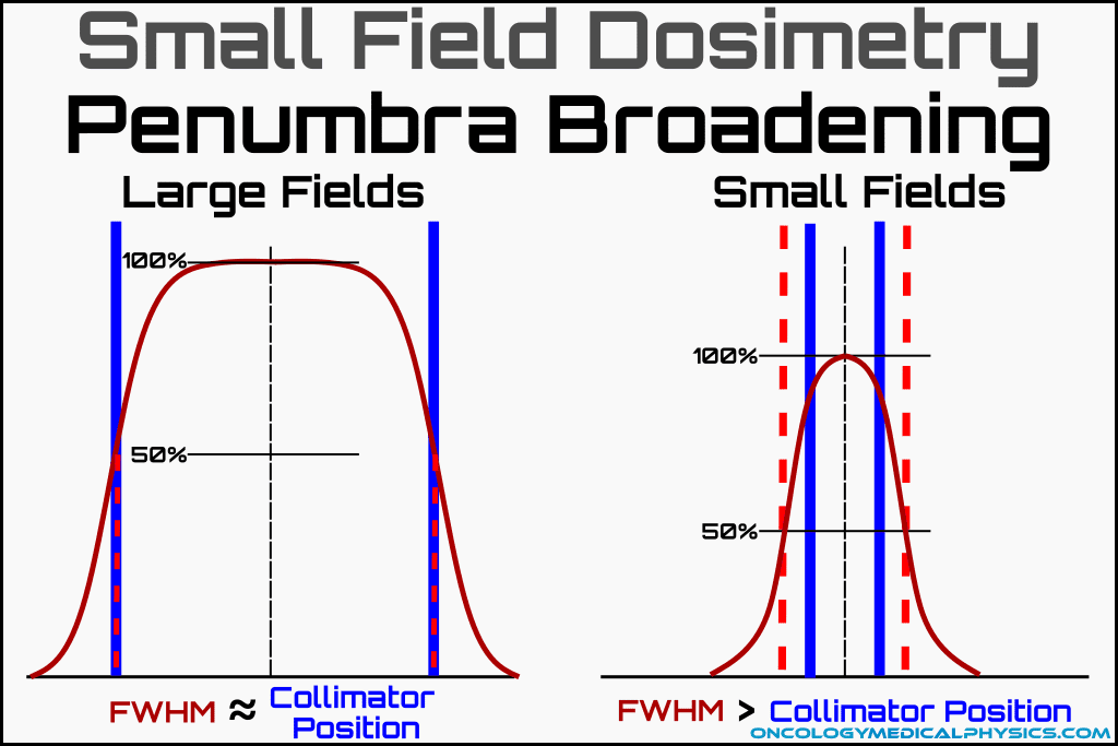
For large fields, the field size is defined by the 50% isodose line at a given distance from the source. By this method the field size setting is equal to the full width at half maximum (FWHM) of the dose profile at the reference depth. This size is reported on the operator station and approximately coincides with the light field.
For small fields this relationship between field size setting and FWHM does not hold. Because of partial source occlusion, FWHM becomes much greater than the field size setting for small fields. This effect is known as penumbra broadening.
TRS-483 uses the radiation field at FWHM as its definition of field size.

The Important of Detector Size
Detectors used in small field dosimetry profile acquisition much have a very small collecting volume to prevent averaging to obscuring the shape of the dose distribution. AAPM TG-106 recommend that the field output be uniform over the collecting volume to +/-1%.
Field Size Uncertainty
For very small fields, where partial source occlusion becomes the dominant factor in penumbra, uncertainty in field size has an exaggerated effect on the shape of the dose distribution.
Uncertainty in the collimation position closest to the source will tend to be dominant.
This is because the positioning error of an object closer to the source is magnified at treatment distance as in the below equation.
![]()
It is for this reason that small treatment fields are defined either by a cone or MLC while the primary collimator, which is closest to the source, is retracted slightly from the field edge.
Key Point: Small MLC shaped fields that are defined on the system as square are often rectangular when measured as FWHM. This effect is caused by leaf design in which the leaf tips have a difference shape than their tongue-and-groove side. As a result, a field defined by the light field as 5x5cm2 may in fact be a rectangular field with an equivalent square field size other than 5x5cm2.
IAEA TRS-483 Methodology
TRS-483 (external link) is a joint effort between the American Association of Physicists in Medicine (AAPM) and the International Atomic Energy Agency (IAEA). Its purpose is to establish a reliable method of determining the output factor for small fields.
Output factor is defined as the ratio of the absorbed dose to water at a point in a non-reference field to absorbed to to water at that point in a reference field.
Terms
Field Size: Field size is defined by the full width at half maximum of the radiation field. That is; field size is defined by the radiation field not the jaw setting readout or light field size.
Machine-Specific Reference Field (MSR): An MSR is a field size used as a reference in place of the traditional 10x10cm2 field size used in TG-51 and other dosimetry protocols. MSR is the used for machines not able to create a 10x10cm2 field such as Tomotherapy, Gamma Knife, and CyberKnife. MSR is usually the largest field a machine is able to make.
Hypothetical Reference Field (\( \Omega^{f_{clin}, f_{msr}}_{Q_{clin}, Q_{msr}} \)): This is the hypothetical field that would result if a machine using MSR could produce a 10x10cm2 field.
Field Output Correction Factor (\( k^{f_{clin}, f_{msr}}_{Q_{clin}, Q_{msr}} \)): A correction factor accounting for the difference in detector response for a clinical (non-reference) and msr field.
Volume Averaging Correction Factor (kvol): The ratio of the absorbed dose to water at the reference point in water without the detector present to the absorbed dose to water over the sensitive volume of the detector, still without the detector present.
Beam Quality Specification in MSR Field (Qmsr): This term represents the energy spectrum of the MSR field. It is either specified as the photon percent depth dose at 10cm depth of the msr field (%dd(10,S)x) or as the ratio of tissue phantom ratios at 20cm to 10cm depth for the msr field (TPR20,10(S)).
Equivalent Square MSR Field Size (S): The size of a square field in which the same amount of phantom scatter is generated as in the non-square field.
Key Point: If a field is smaller than 4cm, it cannot be considered an MSR field for 6MV or higher beams! Source: TRS-483 pg. e1135.
| Quantity | IAEA Symbol | AAPM Symbol |
| Beam quality specifier for msr and conventional 10x10cm2 fields | TPR20,10(10) | %dd(10,10)x |
| Auxiliary specifier for the equivalent square field size S | TPR20,10(S) | %dd(10,S)x |
| Absorbed dose to water calibration coefficient in the machine-specific reference field | \( N^{f_{msr}}_{D,w,Q_{msr}} \) | \(N^{Q_{msr}}_{D,w}\) |
| Absorbed dose to water calibration coefficient in a conventional reference field | \(N^{f_{ref}}_{D,w,Q_{0}}\) | \(N^{Q_{0}}_{D,w}\) |
| Corrected chamber reading in machine specific reference field | \(M^{f_{msr}}_{Q_{msr}}\) | \(M_{Q_{msr}}\) |
| Beam quality correction factor for the conventional reference field | \(k^{f_{ref}}_{Q,Q_{0}}\) | \(k_{Q}\) |
| Beam quality correction factor for the machine specific reference field | \(k^{f_{msr},f_{ref}}_{Q_{msr},Q_{0}}\) | \(k_{Q_{msr}}\) |
| Output correction factor | \(k^{f_{clin},f_{msr}}_{Q_{clin},Q_{msr}}\) | \(k_{Q_{clin},Q_{msr}}\) |
| Field output correction factor | \(\Omega^{f_{clin},f_{msr}}_{Q_{clin},Q_{msr}}\) | \(\Omega_{Q_{clin},Q_{msr}}\) |
Reference Dosimetry
The goal of reference dosimetry is to establish the output, in absorbed dose per monitor unit (cGy/MU) of the reference field.
The reference field is 10 x 10 cm2 for machines able to produce such a field. For machines unable to produce a 10 x 10 cm2 field, a machine specific reference field (MSR) is chosen most frequently as the largest field size the machine can produce.
TRS-483 uses nearly the same methodology for reference dosimetry as AAPM TG-51 or TRS-398 except that it uses the MSR field as the reference field.
Reference Chamber Calibration
The reference chamber must be calibrated for the MSR field. Three approached to reference chamber calibration are acceptable:
1. Chamber directly calibrated for MSR field by the accredited calibration laboratory.
Although this method would be the simplest, direct calibration factors for machine reference fields are generally not available except for Co-60 machines.
![]()
2. Chamber calibrated for standard reference field but used with generic beam quality correction factor.
![]()
3. If neither direct calibration nor generic beam quality data exists, a conventional kQ value for a 10 x 10 cm2 field may be combined with a factor correcting from the standard reference field to the machine-specific reference field.
![]()
Reference Class Dosimeters
A reference dosimeter for an MSR field must meet the requirements of AAPM TG-51 Addendum or TRS-483. The dosimeter should have the following features:
- Be an ionization chamber
- Ionization chambers are well understood devices which take a near primary measurement of absorbed dose by collecting ionization products of air.
- Approximately water equivalent
- This minimizes energy dependence.
- Air communicating
- This allows the chamber to rapidly reach equilibrium and for the mass of air inside to be quantified with an atmospheric pressure reading.
- Water-proof
Specifications for reference class ionization chambers
| Parameter | Specification |
| Chamber Settling |
|
| Leakage |
|
| Polarity Effect |
|
| Recombination Correction |
|
| Chamber Stability |
|
| Chamber Material |
|
Source: Table II TRS-483. Adapted from AAPM TG-51 Addendum.
Relative Dosimetry of Small Fields
Relative output factors for small fields down to about 1cm to 2cm may be measured with small ionization chambers meeting the above specifications of a reference class dosimeter. For smaller fields, even the smallest ionization chambers are found to exhibit large perturbations. These perturbations are largely caused by volume averaging.
Small Field Dosimeters
Common Small field Dosimeters
- Scanning diodes (most common)
- Diamond detectors
- Plastic scintillation detectors
- Micro-ionization chambers with low-Z electrode (for field sizes above 1-2cm)
Detector size
TRS-483 recommends that the volume averaging correction be less than 5%.
Additionally, AAPM TG-106 (external link) recommends that the field output be uniform to within 1% over the detectors sensitive volume.
![]()
Energy Spectrum Response
One less intuitive area of concern for choice of detector is the impact that the small field has on the energy spectrum incident upon the detector. There are two options available to correctly measure dose in a field of non-standard energy spectrum.
1. Determine the effect of the changing energy spectrum on the detector and correct for it.
Although there is some specific data available for this, determining a complete correction factor may require Monte Carlo simulation.
2. Use a detector that minimizes the impact of changes to energy spectrum.
Determining Output Factors
An output factor is the ratio of absorbed dose under given conditions for a small field relative to absorbed dose measured under the same conditions for a reference field.
If a detector is chosen which gives stable response for both the MSR and small field, it may be used alone to determine output factors as:
![]()
For small fields, a suitable detector may not be available. In this case, a technique known as daisy chain is used.
In a daisy chain measurement, a small field dosimeter is cross calibrated with an ion chamber at an intermediate field.
The intermediate field size should be the smallest field that the ioinization chamber can accurately measure.
A 4x4cm2 field is commonly chosen as the intermediate field.
![]()
Another, way to denote the process of daisy chaining (which is not used in TRS-483 and lacks appropriate correction factors) is as:
![]()
Finding small field correction factors
MSR to clinical field correction factors (\(k_{Q_{clin},Q_{msr}}\)) for many chambers have been tabulated and are available in TRS-483 and elsewhere.
Most such correction factors have been determined by Monte-Carlo simulation.
For non-square fields, as defined by full-width-at-half-maximum (FWHM), equivalent square field size must be calculated to find the appropriate correction factor.
![]()
![]()
MSR to intermediate field correction factors (\(k_{Q_{int},Q_{msr}}\)) may not be available. Provided that the intermediate field is not a small field, \(k_{Q_{int},Q_{msr}}\) = 1 may be used. In this way only \(k_{Q_{clin},Q_{int}}\) is required.
Daisy Chaining
Daisy chaining is another common method of determining small field output factor using two dosimeters. Importantly, daisy chaining lacks appropriate small field correction factors and is not recommended by TRS-483.
Below is the simplified process of daisy chaining:
- A reference class ionization chamber is used to measure the reference field and an intermediate field (usually 4x4cm).
- The small field dosimeter then measures the intermediate field and the small field.
- Output factor is computed as:
![]()

Navigation
Not a Member?
Sign up today to get access to hundreds of ABR style practice questions.