
Ionization Chambers
Overview
An ionization chamber consists of a gas filled cavity surrounded by two electrodes of opposite polarity and an electrometer. The electric field established between the electrodes accelerates the radiation produced ions to be collected by the electrodes. This charge is read out by the electrometer and may be converted to absorbed dose.
Three common types of ionization chambers are used in medical physics for reference dosimetry: cylindrical, plane parallel and free air chambers.
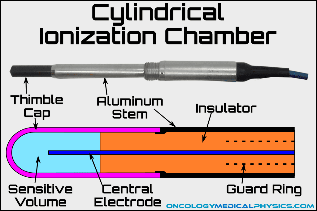
Cylindrical Chambers
Cylindrical chambers are most commonly used in reference dosimetry applications of MV photons and electrons above about 6MeV. Cylindrical chambers, especially farmer chambers, are well characterized and are considered the gold standard of clinical reference dosimetry. Because the of their axial design, the effective point of measurement is upstream of the central axis of the chamber by 0.6rcav for photons and 0.5rcav for electrons.
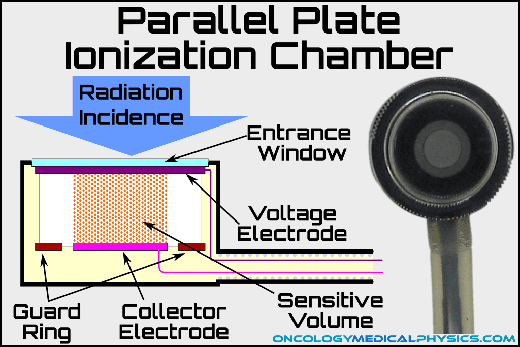
Plane Parallel Chambers
Plane parallel, sometimes called parallel plate, ionization chambers are commonly used in low energy (<6MeV) electron dosimetry as well as in applications where precise measurement location is valued such as measurement of electron percent depth dose distributions. The key advantage of plane parallel ionization chambers is the effective point of measurement is the front (most upstream) plane of the chamber.
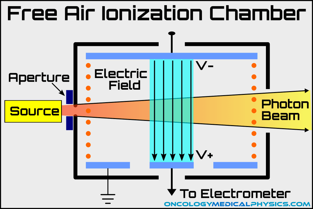
Free Air Chambers
Free air ionization chambers are the instrument of definition for the unit of the Roentgen and, as such, are tied fundamentally to absorbed dose. This makes free air ionization chambers the reference dosimeter of choice for Accredited Dosimetry Calibration Laboratories (ADCLs) but their large size makes them unsuitable for clinical applications.
Farmer Chambers
Key Point: Farmer chambers are thimble ionization chambers widely used in reference dosimetry. Questions regarding farmer chamber design and operation are common on board exams.
- Typical Sensitive Volume: 0.6cc (approximately cylindrical, 0.3cm radius, 2cm length)
- Typical Response: 20nC/Gy
- Effective Point of Measurement:
- Photons: 0.6rcav (~0.18cm) upstream of central axis
- Electrons: 0.5rcav (~0.15cm) upstream of central axis
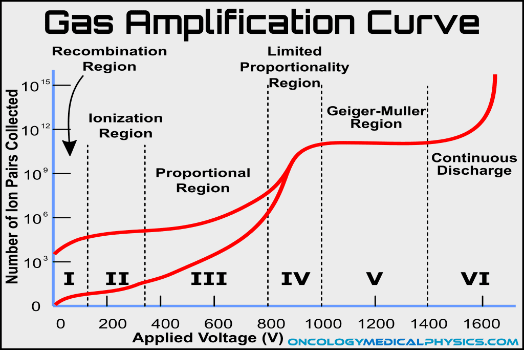
Gas Amplification Curve
The response of an ionization chamber is heavily dependent on the voltage applied between the outer electrode and the central electrode. The gas amplification curve describes the behavior of an ionization chamber as a function of applied voltage.
Region I: Recombination
Response in this region is voltage dependent as well as energy dependent because a large number of ions recombine prior to collection.
Region II: Ionization region
Sufficient voltage to prevent recombination but insufficient voltage to produce secondary ionizations. This is the region used in clinical ionization chambers because the measured signal is directly proportional to the number of ionizations produced by incident radiation.
Region III: Proportional region
Response is proportional to energy collected and to the applied voltage. Proportional counters operate in this voltage range.
Region IV: Limited proportionality region
Response to collected energy diminishes while response to applied voltage increases. This voltage region is not used.
Region V: Geiger-Muller region
Townsend avalanche creates a large number of secondary avalanches. Like an explosion burns until the fuel source runs out, a Townsend avalanche produces secondary electrons until the electrons neutralize the local electric field preventing further ion production.
Region VI: Continuous discharge region
The chamber continually arcs due to excessive applied voltage.
Comparison of Common Dosimeters
| Device -Accuracy | Common Uses | Advantages | Limitations |
|---|---|---|---|
| Ion Chambers ±1% | -Reference Dosimetry -Percent Depth Dose Distributions | -Best understood -Sub 1% accuracy possible -Low energy dependence | -Size limitations -ADCL calibration required |
| Diode Detectors ±2-3% | -Small field dosimetry -Array devices -Electron PDD | -Small volume -Rapid readout -No external bias | -Temperature dependence (0.5%/C) -Dose rate dependence -Energy dependence |
| Film ±2-5% | -Planar dose distributions -Electron PDD | -Best spatial resolution (μm) -Large area measurement -Persistent dose record -Tissue equivalent (radiochromic only) | -Delayed readout -Batch-to-batch variation -Chemical development (radiographic only) |
| Luminescent Dosimeters ±3% | -In Vivo Dosimetry -Personnel dosimeters -End-to-end testing (IROC) | -Small size -Low MV energy dependence | -Delayed readout -Signal loss over time -Supralinear response with accumulated dose |
| MOSFET Detectors | -In vivo dosimetry -Small Field Dosimetry -Surface dose | -Extremely small effective volume -Permanent dose record -Instant readout | -Finite life (~100Gy) -Energy Dependence -Temperature Dependence -Sensitivity changes with accumulated dose |
| Plastic Scintillators | -Small Field Dosimetry -Array Measurements -Electron measurements | -Small volume -Near water equivalent -Dose and rate independent | -Noise, especially Cherenkov Radiation -Sensitivity change with plastic yellowing -New technology, few vendors |
Navigation
Not a Member?
Sign up today to get access to hundreds of ABR style practice questions.