MRI Artifacts
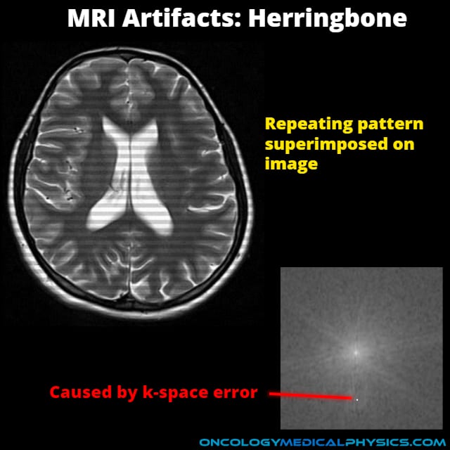
MRI artifacts arise from a variety of sources including MR hardware, room shielding, patient motion, tissue heterogeneity, foreign bodies, sampling resolution and k-space errors. Ability to identify and explain basic MRI artifacts is important because it allows one to distinguish between anatomy and artifact. Further, understanding the source of an artifact makes eliminating or reducing the clinical impact of an artifact possible.
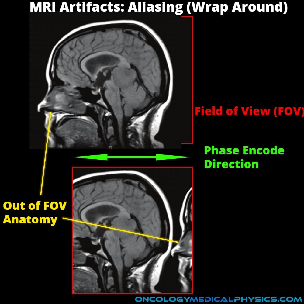
Aliasing (Wrap Around) Artifact
Appearance
- Anatomy outside of the field-of-view (FOV) is superimposed on the opposite side of the image.
- Aliasing is most commonly seen in the phase encoding direction.
Causes
- Sampling at below the Nyquist frequency (< twice the RF frequency of the voxel) causes the apparent frequency to be lowered in a process known as aliasing.
Artifact Reduction
- Many scanners have automatic wrap around removal either by oversampling or by applying a low pass filter prior to analog-to-digital conversion.
- Change phase encode direction.
- Increase field-of-view.
Chemical Shift
Appearance
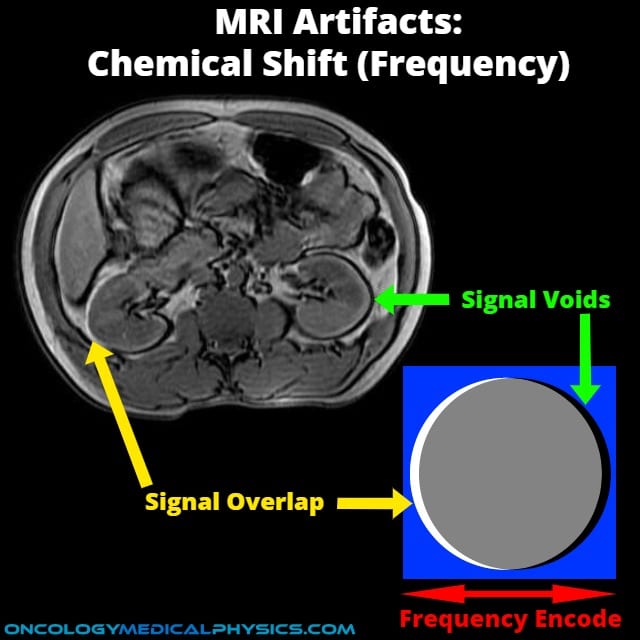
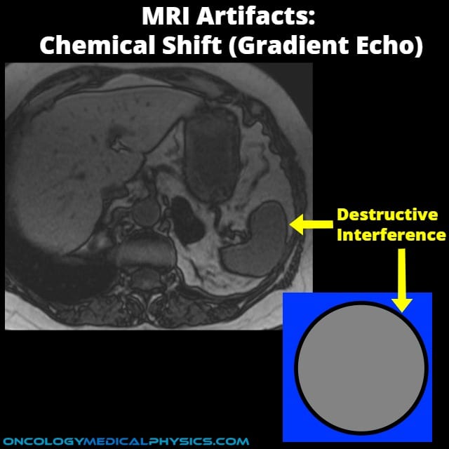
- Dark or light edges on borders of structures with different chemical compositions.
Causes
All chemical shift artifacts occur because of differences in the intrinsic shielding of bodily chemical structures. This causes apparent displacement in either the frequency or phase encoding directions.
- Frequency encoding
- Occurs as a direct result of small changes (3-4 ppm) in precession frequency resulting in signal being mapped to a different location in the frequency encoding direction.
- Appears as displacement with a light edge on one side (overlap) and a dark edge on the other (signal void).
- Destructive phase shifts
- Occurs in gradient echo imaging as the result of constructive and destructive interference in dephasing and rephasing the echo.
- Appears as dark border around the entire structure.
Artifact Reduction
- Use higher bandwidth.
- Use lower field strength scanner.
- Avoid gradient echo imaging or adjust gradient echo timing.
Key Point: Chemical shift magnitude is proportional to field strength as governed by the Larmor frequency.
Geometric Distortion
Appearance
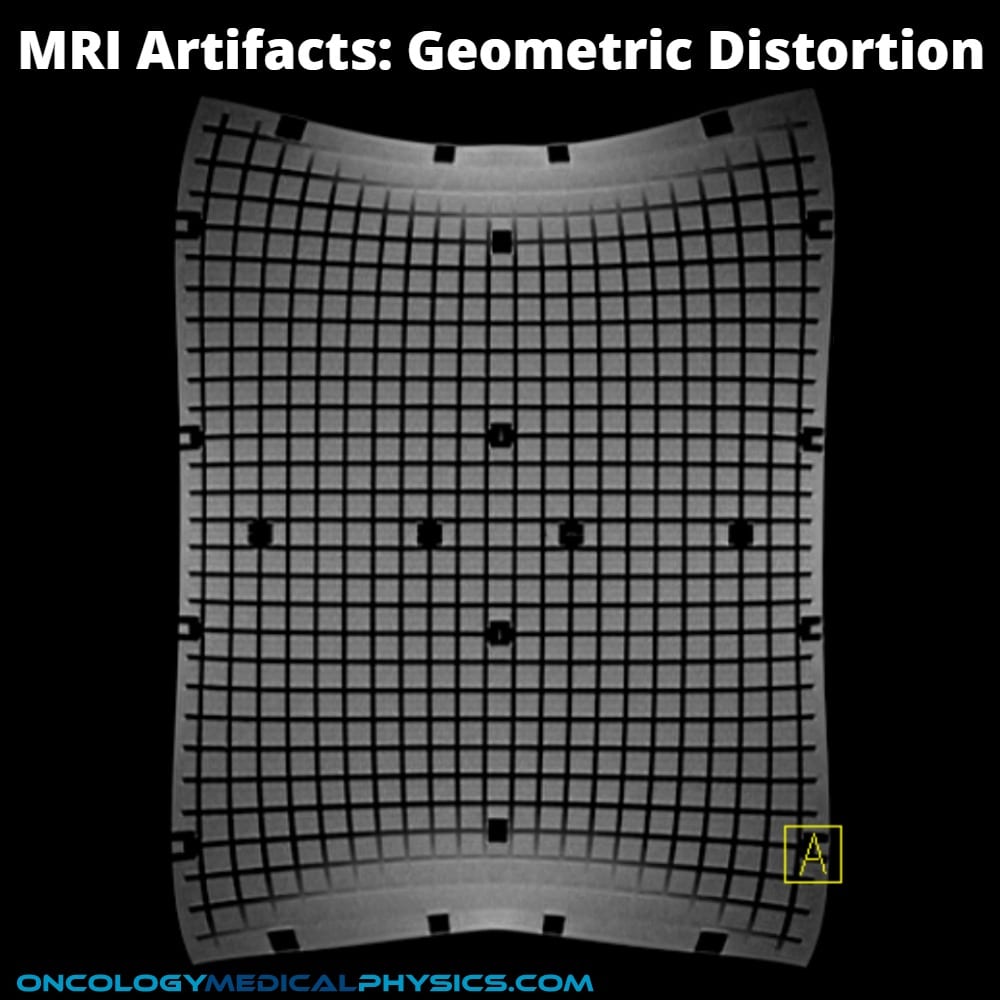
- Appears as physical distortion of the image.
- May not be readily apparent in tissue but can be evaluated using grid phantom.
Causes
- Geometric distortion may be the result of non-uniformity of the magnetic field leading to inaccurate encoding the spatial position.
- May be caused by the machine itself or by areas of variable susceptibility within the patient (i.e. implanted devices).
Artifact Reduction
- Use lower field strength scanner.
- Place regions of interest near field center which is area of lowest distortion.
- Regular quality control to assure proper shimming.
Key Point: A major challenge in using MRI for radiation therapy treatment planning is geometric distortion.
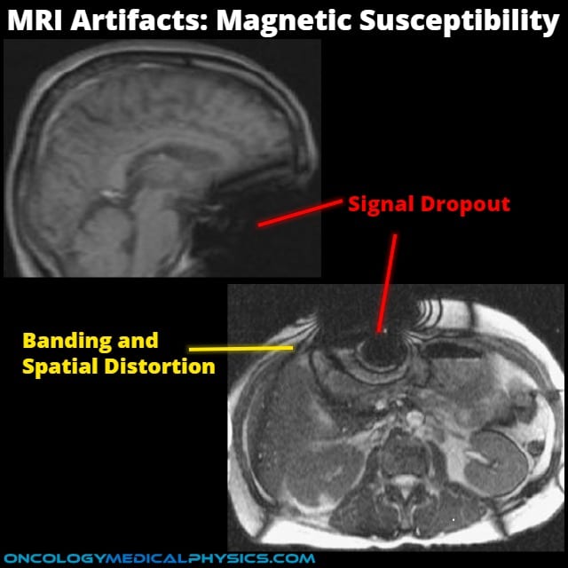
Magnetic Susceptibility Artifact
Appearance
- Most often appears as darkening (signal dropout) in a portion of the image.
- May also appear as brightening or spatial distortion.
Causes
- Results from drastic changes to the local magnetic field arising from inclusion of ferromagnetic, paramagnetic, or diamagnetic materials in the scan.
- Ferromagnetic materials (iron, nickel, etc.) cause strong artifacts like signal drop out.
- Paramagnetic and diamagnetic materials (those weakly attracted to or repelled by magnetic fields respectively) cause lesser artifacts.
Artifact Reduction
- Remove metal from scan.
- Use short echo time image sequences.
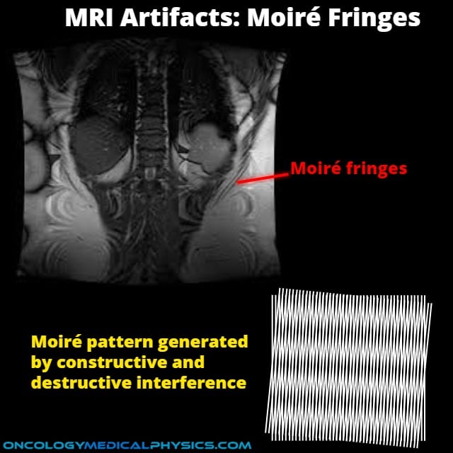
Moiré Fringes Artifact
Appearance
- Repeated irregular bands of light and dark.
Causes
- Signals from different phases are superimposed yielding constructive and destructive interference of signal intensity.
- Non-uniformity of magnetic field.
Artifact Reduction
- Improve field uniformity by shimming.
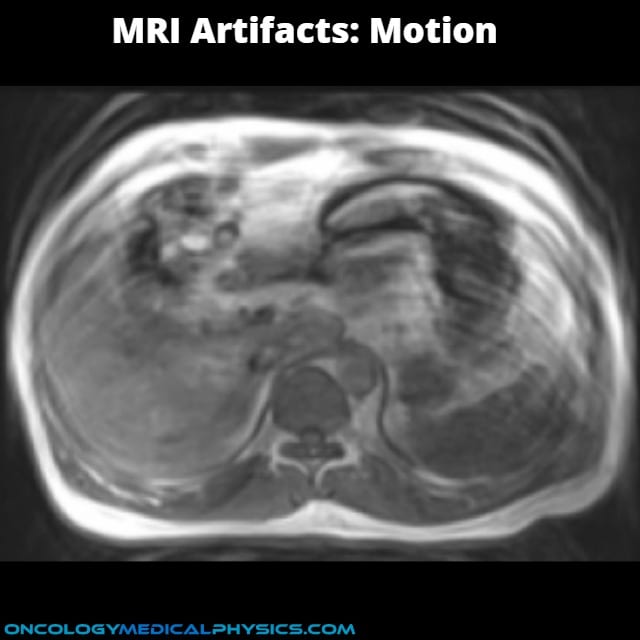
Motion Artifact
Appearance
- Faint copies of the image (known as ghosts) are superimposed on the image.
- Ghosting typically occurs along the phase encoding direction.
Causes
- Motion (including involuntary motion and blood flow) causes anatomy to be imaged at different locations.
Artifact Reduction
- Reduce patient motion
- Choose faster acquisition sequences
- Use PROPELLER acquisition sequences
Truncation (Ringing) Artifact
Appearance
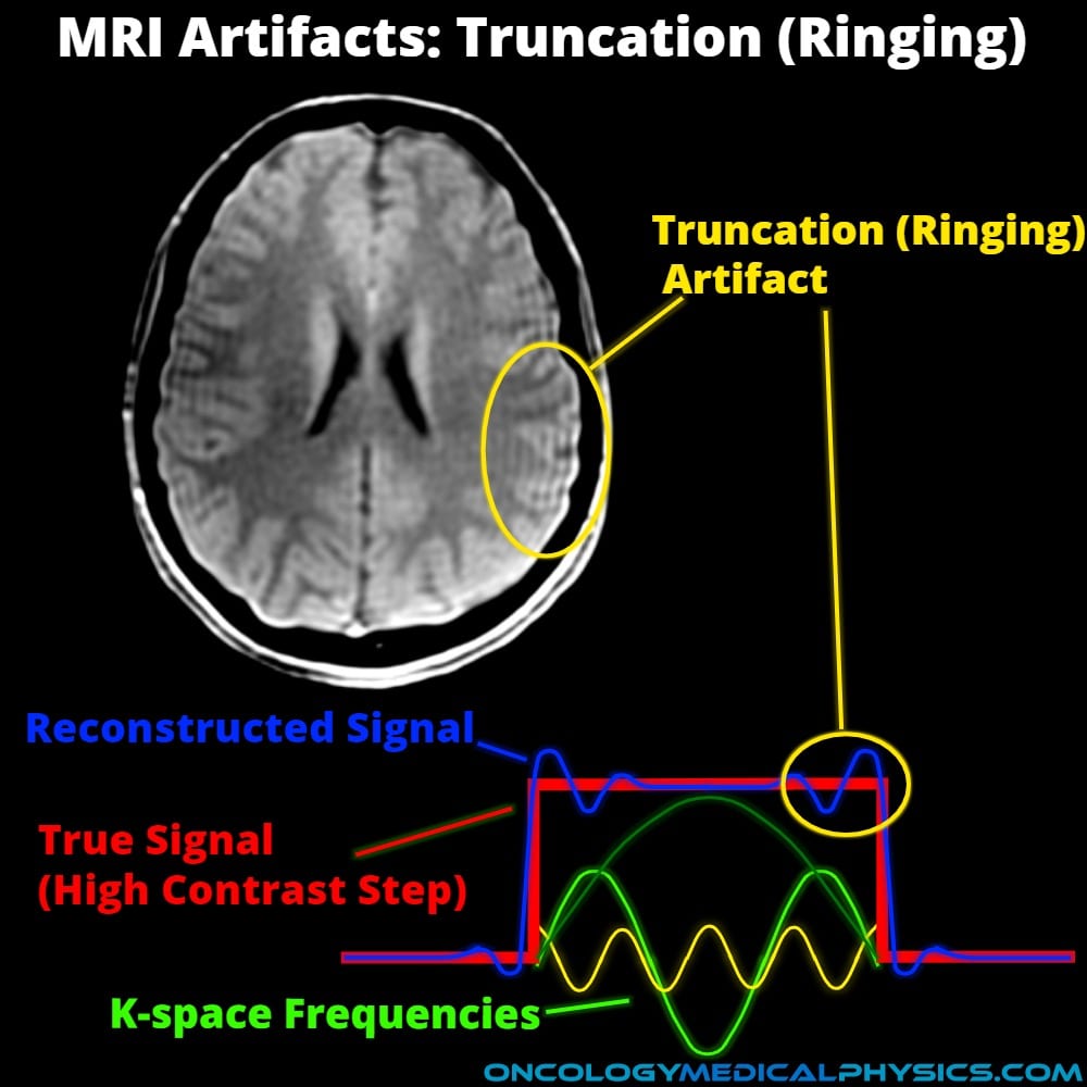
- Fine parallel lines adjacent to a high contrast interface.
- Can appear as an anatomical structure, especially in the spinal cord.
Causes
- Caused by the inverse Fourier transform used to convert k-space map into image.
- A step gradient (or other very sharp edge) requires a very large (nearly infinite) number of varied frequency sin waves to construct. Practically, only a finite number of frequencies can be sampled causing an oscillation in the resulting image.
- Since the Fourier series was cut short (truncated), the artifact is referred to as truncation.
Artifact Reduction
- K-space post-processing can reduce Truncation artifacts.
Zipper Artifact
Appearance
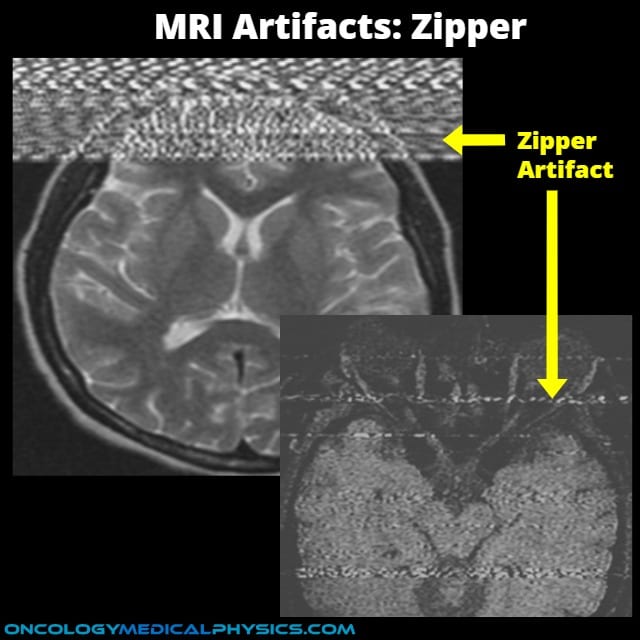
- Interference across one or more rows, most commonly in the phase encode direction.
Causes
- Most commonly caused for feed-through in which an outside RF signal is picked up by the receiver system.
- Phase encode direction.
- May also arise from stimulated echoes resultant of poor slice selection profiles or poorly adjusted RT-transmitters.
- Frequency encode direction.
Artifact Reduction
- Assure room door is closed for complete RF shielding.
- Move patient monitoring system (e.g. anesthesia equipment) as far away from the scanner as possible.
Navigation
Not a Premium Member?
Sign up today to get access to hundreds of ABR style practice questions.

