Film Dosimeters
Overview
Film may be used in radiation measurement, especially for measurement of relative dose distributions. The dosimetric accuracy of film is, however, limited to 2-5% because film measurement is subject to many compounding sources of error (measurement conditions, development, readout, etc).
There are two distinct types of film: radiographic film and radiochoromic film. Radiographic film is similar to that used in older radiography applications and requires chemical development. Chemical development adds cost and introduces significant variability in dose measurement.
Radiochromic film is self-developing via a polymerization reaction. This self-development feature has cause radiochromic film to largely supersede radiographic film for dosimetry purposes.
Dose Measurement
- Film is oriented with appropriate side facing beam and irradiated.
- Film may also be oriented parallel to the field for percent depth dose measurements.
- If radiographic, film is chemically processed. If radiochromic, time delay after exposure as image producing reactions occur.
- Film is read out on calibrated scanner.
- This will measure optical density.
- Optical density is converted to absorbed dose via calibration.
Optical Density
Optical Density (OD), the log base 10 of the fraction of light transmitted through an unexposed film to the light transmitted after exposure.
![]()
- I0 is the light collected without film.
- I is the light collected after passing through film.
- T is the transmittance; the ratio of the light transmitted through film to the light transmitted without film.
Hurter and Driffield (H&D) Curves
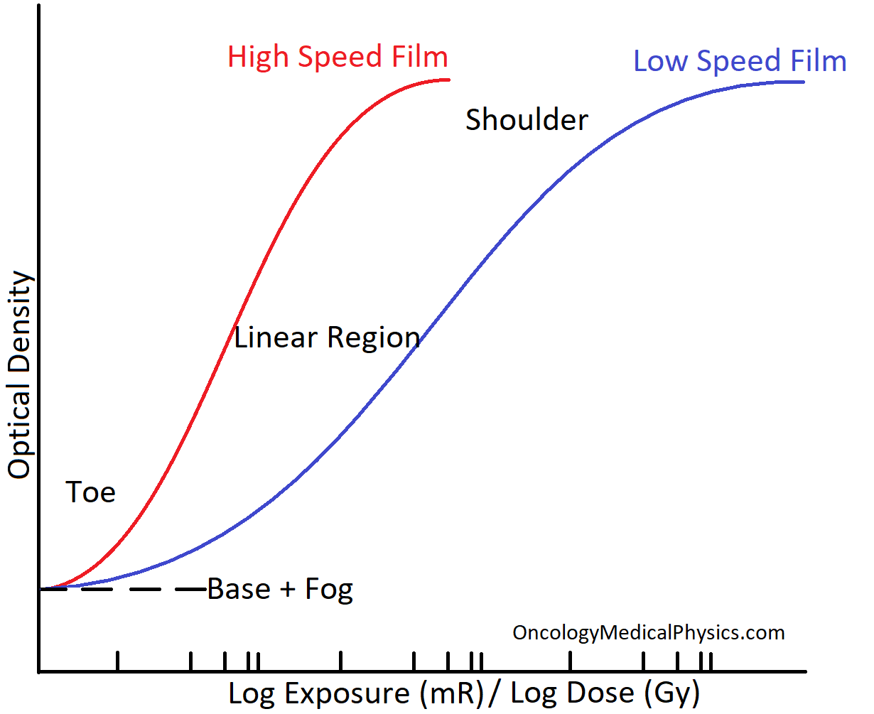
H&D curves are used to relate the exposure or dose to optical density. Most H&D curves used for dosimetry purposes report optical density as a function of log base 10 of dose.
Film Speed: Fast film will have a greater increase in optical density with dose but will also have a more limited range of optical densities. Slower film provides better range and dose resolution. Faster film is more appropriate for dose reduction in imaging purposes.
Gradient: The slope of the curve in the linear region. Fast films have a higher gradient.
Latitude: The range of exposures in the linear region. This is also referred to as the range.
Linear Region: This is the useful region in which optical density is proportional to log of exposure.
Toe, Shoulder: These regions are not clinically useful as the relationship between exposure and optical density is non-linear.
Fog: Darkening of the film due to background radiation or light exposure (for radiographic film).
Base: The natural attenuation of the film without exposure or fog.
Types of Film
| Dose Accuracy | Advantages | Disadvantages | |
|---|---|---|---|
| Radiographic | 3-5% |
|
|
| Radiochromic | 2-3% |
|
|
Radiographic Film
Radiation Measurement Process
- When radiation hits the film, loosely bound electrons are freed.
- These electrons aggregate around impurities and form a negative charge.
- This negative charge attracts the Ag+ ions leaving behind neutral (metallic) silver. This is the latent image.
- Latent image will be magnified a billion fold (~109)
- The film is developed in a 4-step process
- The developer is applied to the emulsion. This greatly amplifies the amount of metallic silver and the latent image.
- Acetic acid (referred to as the stop bath) is applied which stops further development.
- The fixer (Sodium Thiosulphate) dissolves all undeveloped grains thereby fixing the image.
- The image is washed to remove chemicals and dried.
- Finally, the film is read out on a calibrated optical digitizer.
Key Point: The latent image consists of metallic silver atoms and is not visible without development. Latent images can be formed by as few as 10 silver atoms. There are more commonly many thousands of metallic silver atoms in the latent image because a single X-ray quanta is able to produce over 1000 silver atoms.
Radiographic Film Construction
Plastic Base: provides the structure of the film.
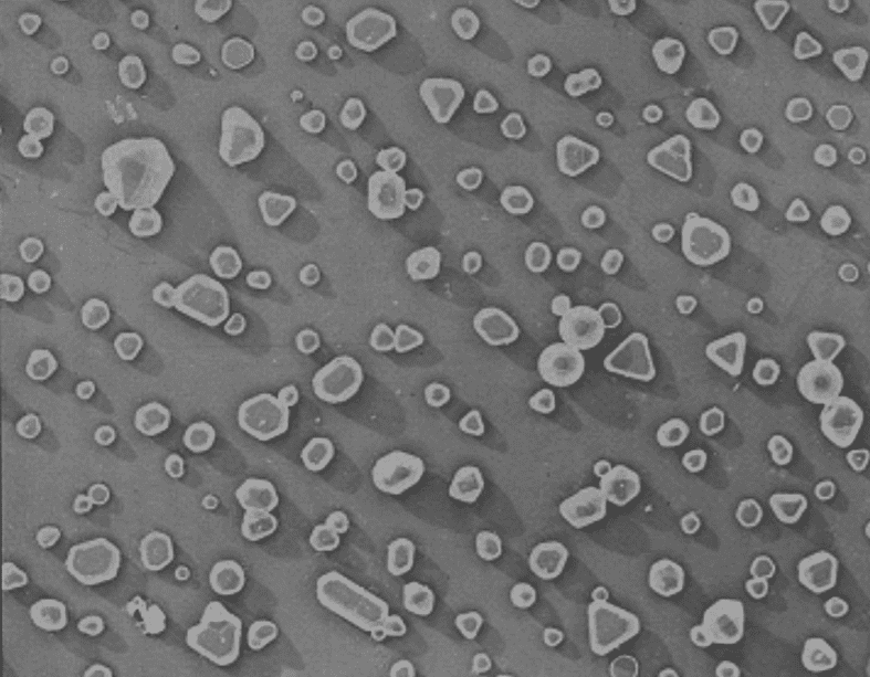
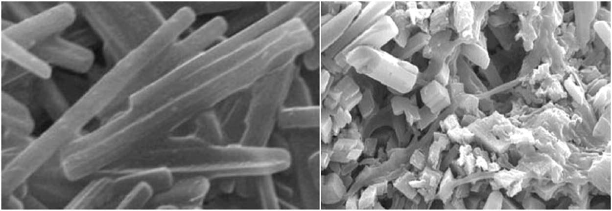
Silver Bromide Emulsion: is the active layer of the film consisting of Ag+ and Br- ions.
- Grains are 0.1 – 3 μm in diameter
- 109 to 1010 grains per square centimeter
Gelatin Protective Layer: serves to keep the silver bromide grains well dispersed and to protect unexposed grains during development.
Radiochromic Film
Radiochromic, sometimes referred to as GafChromic, film used a radiation induced polymerization action to produce darkening of the film proportional to absorbed dose.
Radiation Measurement Process
- Radiation incident on the active layer induces a polymerization reaction.
- As the active layer polymerizes, it becomes partially opaque in proportion to the incident dose. This process continues for several hours and the time between measurement and readout must be controlled.
- After 1-24 hours, the film is read out on a calibrated optical digitizer. Near immediate readout is possible but results in decreased measurement precision.
Radiochromic Film Construction
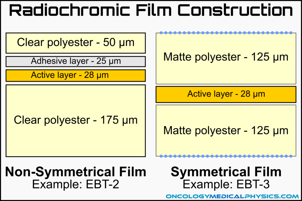
Base Layer: Polyester (Mylar) base provides structure to the film.
Active Layer: Consists of radio-sensitive chemicals which polymerize into optically opaque polymers upon irradiation. This is a chemical reaction which takes approximately 24 hours to complete, although most of the development occurs in the first hour.
Symmetrical and Non-Symmetrical Designs: Although most current films are constructed symmetrically, older films have been constructed asymmetrically. Asymmetrical construction requires attention to orientation during measurement and readout to avoid introduction of systematic error.
EBT 2 is a common example of asymmetrical construction. Although it was later shown that this had little influence on measured dose distribution, EBT 3 was introduced with a symmetrical design.
Optical Digitizers and Film Scanners
Optical digitizers, sometimes referred to as film scanners, are used to convert the film optical density distribution to digital form for analysis. Digitizers typically consist of a light source and a CCD or SMOS image sensor. After digitization, the optical density map may be converted to a dose distribution by means of a calibration curve.
Comparison of Common Dosimeters
| Device -Accuracy | Common Uses | Advantages | Limitations |
|---|---|---|---|
| Ion Chambers ±1% | -Reference Dosimetry -Percent Depth Dose Distributions | -Best understood -Sub 1% accuracy possible -Low energy dependence | -Size limitations -ADCL calibration required |
| Diode Detectors ±2-3% | -Small field dosimetry -Array devices -Electron PDD | -Small volume -Rapid readout -No external bias | -Temperature dependence (0.5%/C) -Dose rate dependence -Energy dependence |
| Film ±2-5% | -Planar dose distributions -Electron PDD | -Best spatial resolution (μm) -Large area measurement -Persistent dose record -Tissue equivalent (radiochromic only) | -Delayed readout -Batch-to-batch variation -Chemical development (radiographic only) |
| Luminescent Dosimeters ±3% | -In Vivo Dosimetry -Personnel dosimeters -End-to-end testing (IROC) | -Small size -Low MV energy dependence | -Delayed readout -Signal loss over time -Supralinear response with accumulated dose |
| MOSFET Detectors | -In vivo dosimetry -Small Field Dosimetry -Surface dose | -Extremely small effective volume -Permanent dose record -Instant readout | -Finite life (~100Gy) -Energy Dependence -Temperature Dependence -Sensitivity changes with accumulated dose |
| Plastic Scintillators | -Small Field Dosimetry -Array Measurements -Electron measurements | -Small volume -Near water equivalent -Dose and rate independent | -Noise, especially Cherenkov Radiation -Sensitivity change with plastic yellowing -New technology, few vendors |
Navigation
Not a Member?
Sign up today to get access to hundreds of ABR style practice questions.


