
Linac Subsystem Design
Treatment Head Components
Dual Scattering Foils
Linear accelerators typically use a dual scattering foil design to spread the pencil electron beam into a wide uniform beam of clinically useful area.
Primary (Upper) Foil
This foil serves to both initially scatter the beam and as a vacuum/air interface.
Primary foil is comprised of a high Z material such as Tantalum (Z = 73) or Gold (Z = 79). This is because these materials have a high ratio of linear scattering power to collision stopping power. That is, they are desirable because the are efficient at scattering.
Typical thickness is approximately 0.05-0.4mm.
Secondary (Lower) Foil
The lower scattering foil further scatters the beam but is typically made of a low Z material such as aluminum (Z = 13) in order to reduce Bremsstrahlung photon production.
Typical thickness is approximately 1-3mm.
Electron Applicator
The electron applicator is a collimation device which is affixed to the treatment head for electron therapy deliveries. The applicator consists of several collimators, called scrapers, which provide collimation close to the patient surface.
Electron applicators may have a custom-shaped cutout placed at the level of the lowest scraper to provide the final beam shape. These cutouts may be molded of Cerrobend or cut, often of copper.
Key Point: Electron applicators are necessary because charged electrons scatter regularly in air. Without a collimator placed close to the patient/phantom surface, the electron beam would have a very large penumbra.
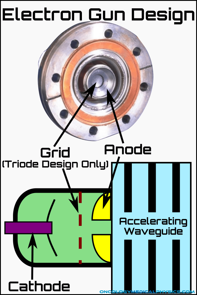
Electron Gun
The electron gun is responsible for injecting electrons into the accelerating waveguide. It accomplishes this using a heated cathode which thermoinically "boils-off" electrons. These electrons are then accelerated toward a grounded perforated anode and are focused into a pencil beam by a focusing coil. Finally, electrons pass through the anode into the accelerating waveguide where they are accelerated.
There are two main types of electron gun used in linacs; diode type and triode type. The diode type operates as explained above, using only the heated cathode and a grounded anode. The cathode design adds a grid between the cathode and grounded anode. Voltage of the grid is pulsed in time with the accelerating waveguide, only allowing electrons to pass at the optimal moment for acceleration.
Accelerating Waveguides
The accelerating waveguide in its simplest form is an evacuated metal tube separated by donut shaped discs into several cavities. Electrons are accelerated through the holes in the discs using an oscillating electric field supplied by the radio-frequency generator (magnetron or klystron) and modulator. The frequency of electric field oscillation is in the microwave range between the L-band (1GHz) to the X-band (10 GHz). The most common frequency is 2.856GHz which is with the S-band.
As the electrons first accelerate from near rest, they initially take on energy from the electric field in the form of additional velocity. Thus the first few cavities in the accelerating waveguide become progressively longer as the electrons take less and less time to traverse the cavity. The divider aperture is also large in the first section of the waveguide and progressively narrows. Narrowing of the apertures causes the electric field to act as a funnel, compressing the electron cloud into bunches. Hence this first section is known as the buncher.
As the electrons approach the speed of light, more and more of their energy gain comes in the form of additional relativistic mass rather than additional velocity. As a consequence, the cavities beyond the buncher are short and uniform in length. Accelerating waveguides may be either of the traveling-wave or standing-wave based on the time dependent variation of their electric field.
Key Point: Medical linacs use an oscillating electric field rather than a static field, like those used in diagnostic X-ray generators, because static high potential electric fields cause electrostatic discharge within the accelerator. This discharge limits the maximum energy of a static field accelerator to about 1MeV.
Accelerating Waveguide Facts
- Standing-wave designs are shorter than traveling-wave designs and, as a result, are much more common.
- Clinical accelerator waveguides may be as short as 0.3m for low energy systems or over a meter for high energy systems
- Only about 33% of electrons emitted to the accelerator waveguide are actually accelerated.
- A circulator is used to prevent reflected waves from reaching the magnetron/klystron.
Traveling-Wave Waveguides
As the name implies, the microwave electric field in a traveling-wave waveguide moves down the structure in a manner similar to a wave on a beach. In this analogy the electrons are accelerated through the waveguide in a manner similar to a surfer. By the far end of the waveguide, not all of the electric field’s energy has been absorbed by the electron and must be absorbed by a resistive material in the last cavity to prevent potentially damaging energy reflection. Because of the nature of the standing wave, only 1 in 4 cavities may be involved in accelerating the electrons at a given time.

Standing-Wave Waveguides
The microwave electric field in a standing wave design changes its amplitude with time rather than its position. The standing-wave is set up by allowing the energy remaining at the end of the waveguide to be reflected backward. That is, the standing-wave design actually uses a forward traveling wave and a backward traveling wave to produce a net stationary waveform. Energy reflected back must be prevented by a circulator from reaching, and potentially damaging, the klystron or magnetron.
Changing amplitude of the wave rather than position is advantageous because, although the wavelength remains 4 cavities long, every other cavity may be used to accelerate the electron. Further, since every other chamber is a node, has no electric field at all any time, there is no need for the accelerating electrons to pass through it. Hence these coupling chambers may be removed from the beamline path further reducing the required waveguide length while still coupling the accelerating chambers. The net result of these techniques is a significant reduction in the accelerating waveguide length.

Microwave Generators
Magnetrons and Klystrons are used in modern linear accelerators to produce the microwaves needed to accelerate charged particles.
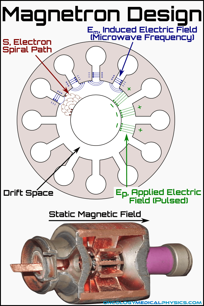
Magnetrons
Magnetrons are microwave generators which operate as high power oscillators driven by electrons traveling in interacting magnetic and electric fields.
Magnetrons are made of a copper housing milled with multiple internal resonance cavities. The copper housing serves also as an anode opposite a centrally located cathode. Ohmic heating of the cathode causes thermionic emission of electrons into the space between the anode and cathode. A static magnetic field is applied to perpendicular to the electric field between the anode and cathode (i.e. along the axis of the magnetron cylinder).
A pulsed DC electric field, EP, is applied between the anode and cathode causing the electrons to accelerate toward the anode. The presence of the magnetic field causes the electrons to curve. When some electrons reach the anode wall, the cause a local reduction of charge. This small gradient in charge along the surface of the anode generates a small electric field, Em, which causes a current to flow along the inner surface of the anode. Some time is required to even out the surface charge of the anode. During this time, additional electrons will strike the more positively charged areas of the anode. The net effect is formation of an oscillating current along the surface of the anode as the current attempts to equalize charge at one spot, then another. Oscillating currents flowing around the cavities cause electrons to travel along spiral paths, S, releasing microwave energy.
Klystrons
A klystron is a microwave amplifier used in higher energy (>12MeV) linear accelerators. Because the klystron is an amplifier rather than a generator, low powered microwaves must be provided to the klystron for amplification by a microwave oscillator.
Klystrons consist of an elongated tube, called the drift tube, separating two or more cavities and an electron gun. The electron gun uses a heated cathode to emit electrons which are accelerated toward an anode into the first cavity. The first cavity is called the buncher because the input low powered microwaves cause the electrons to bunch up as they travel down the drift tube. When the electrons reach second cavity, called the catcher, they induce a retarding electric field which causes additional electrons to decelerate quickly. This deceleration releases energy at the microwave frequency that applied in the buncher but at a much higher amplitude.
")
Klystron Operation
- The klystron generates electrons by heating a filament within the cathode. A momentary negative pulse is applied to the cathode, propelling the electron cloud toward the anode and into the buncher cavity. Energy imparted at this stage will be used to increase the amplitude of the microwaves.
- Low-powered microwaves enter the buncher, where an alternating electric field, induced by the input low powered microwave, slows some electrons while accelerating others.
- The electrons enter a drift tube where, because of their different velocities, they are spatially compressed into bunches.
- As each bunch of electrons passes thought the catcher, they bring along a periodic change in electric field intensity (i.e. the field near the bunches is stronger than the field away from the bunches). They are timed in such a way that the catcher rings – like a bell – at its resonant frequency. This signal is collected as a high energy microwave.
- The output signal is larger than the input signal because nearly all of the electrons entering the catcher are decelerated, thus giving up energy to the catcher cavity. This is much more energy than is imparted to the electrons in the buncher because, at that stage, roughly the same number of electrons are slowed as accelerated.
- The energy used for this amplification comes from the initial acceleration between the anode and the cathode.
- Finally, an electron collector absorbs the electrons, turning their remaining kinetic energy into heat which must be dispersed.
Key Points
- Magnetrons generate microwaves
- Klystons amplify microwaves so require an RF generator input
- Both Klystrons and Magnetrons operate using resonance
- Magnetrons are typically used in accelerators with energies less than 12MeV
- Klystrons are preferred for high energy applications
- Magnetrons are lower cost but also less stable than Klystrons
- Magnetrons are slightly more efficient than Klystrons (60% vs 50%)
Navigation
Not a Member?
Sign up today to get access to hundreds of ABR style practice questions.