
Luminescent Dosimeters
Overview
Luminescent dosimeters are crystal structures which are able to trap and store energy when irradiated. This energy is later released via luminescence in the form of visible light. Measurement of emitted light may be used to determine the dose delivered to the dosimeter.
TLDs vs OSLDs
| Accuracy | Chemical Composition | Advantages | Disadvantages | |
|---|---|---|---|---|
| Thermoluminescent Dosimeters (TLD) | ~3% | LiF:Mg, TI |
|
|
| Optically Stimulated Luminescent Dosimeters (OSLD) | ~3% | Al2O3:C |
|
|
Dose Measurement
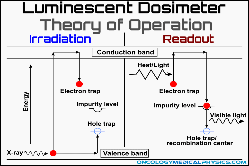
- Incident ionizing radiation creates an electron-hole pair in the crystal structure.
- The liberated electron is promoted to the conduction band and migrates to the electron trap. At the same time the hole migrates along the valence band to a hole trap.
- Energy (in the form of heat for a TLD or light for an OSLD) is imparted to the electron and hole allowing them to escape their traps. This causes the electron-hole pair to recombine at a luminescent center and release light.
- Emitted light is measured by a photomultiplier tube or camera (CCD or CMOS). This light is used to determine absorbed dose.
Crystal Structure
Energy Bands: The crystalline structure of luminescent dosimeters gives rise to delocalized electronic states referred to as energy bands.
Valence Band is the band of electron orbitals that can donate an electron to the conduction band when excited. This is simply the outermost electron orbital that is occupied by electrons.
Conduction Band is the energy band that excited electrons can enter when leaving the valence band. Electrons in the conduction band are able to move freely producing electric current. Simply put, the conduction band is able to conduct current.
Band Gaps are the difference in energy between the valence and conduction bands. The size of the band gap determines the minimum energy required for an excited valence electron to enter the conduction band. Band gap size determines whether the material is a conductor (no band gap), a semiconductor, or an insulator (large band gap).
Crystal Lattice Imperfections: Imperfections in the crystal lattice create occupiable energy levels withinthe band gap. These energy levels are known as traps because electrons can remain trapped in these energy levels until freed. There are three important types of imperfections:
Trap Centers: are meta-stable energy states for charge carriers (electrons and holes) elevated out of the valence band. Trap centers allow the detector to hold some of the absorbed dose energy until readout.
-
- Depth of the trap relates to the amount of energy required to escape the trap. (i.e. shallow traps may be escaped under ambient conditions but deep traps require a great deal of heat/light energy for the charge carrier to escape).
- F-center (the most common trap) is characterized by an anion vacancy in the crystal.
- Mangesium dopants add trap centers.

Luminescent (Recombination) Centers: are imperfections that allow electron/hole pairs to recombine and, in the process, emit the light used to determine absorbed dose. Trapped electrons must be excited by light or heat to enter a luminescent center.
-
- Titanium dopants add luminescence centers
Competitive Centers: also trap charge carriers but do not contribute to luminescence other than removing the charge from being able to recombine. Filling of competitive centers is responsible for the increase in sensitivity of TLDs at high doses (supralinear response).
Doping: Imperfections can be intentionally added to a crystal through a process called doping. Doping allows control over the properties of a luminescent dosimeter by modifying the content of trap, luminescent and competitive centers. Common dopants include Mg, Ti and C.
Key Point: Luminescent detectors exploit crystalline imperfections to trap radiation energy within the crystal. This energy can then be released as light and used to determine absorbed dose.
Thermoluminescent Dosimeters (TLD)
Optical Readout
Heating causes the TLD to emit photons which are measured in real time using a photomultiplier tube (PMT) or optical camera (CCD or CMOS). Heaters may either use an ohmically heated plate or heated nitrogen gas.


Glow Curve
A glow curve is a graph of luminescence as a function of TLD temperature.
The probability of escaping a trap center increases with temperature and decreases with trap depth. Cumulative probability of escaping a center is then proportional to both temperature and time under the temperature. This results in distinct glow peaks on the glow curve. Use of a consistent heating protocol (rate of temperature increase) is also important for this reason.

Reusing TLDs
Annealing (Preparation for Reuse)
Annealing is a heating process by which trap centers are emptied and redistributed through out the crystal lattice. As with readout, consistent heating protocol during annealing is important to assure consistent TLD response.
Below is one common annealing protocol:
- Heat to 400°C for 1 hour to reset lattice/impurity structure.
- Reduce heat to 80°C for 24 hours to rearrange the traps that result in peak 2 (glow curve image).
Supralinearity
The response of TLDs increases (i.e. TLDs become more sensitive) with repeated use. This increases sensitivity, known as supralinearity, is caused by a decrease in the availability and efficiency of competitive centers. There are two reasons for this decrease:
- As competitive centers become increasingly populated, the odds of a charge carrier encountering an available competitive center decreases.
- Energy distance between neighboring trap and luminescence centers decreases. This decreases probability of the charge carrier encountering a competitive center once freed from a trap.
Optically Stimulated Luminescent Dosimeters (OSLD)
Optical Readout
Light emission is stimulated by illuminating the crystal. Illumination may be supplied by lasers, LEDs or fluorescent lamps. Luminescent photons may be measured with a photomultiplier tube or camera (CCD or CMOS).
The entire illumination process takes only about 1 second and releases only about 0.05% of the stored luminescence. This allows multiple readouts of the same measurement.
Light Source Rejection
The wavelength of illumination light source is different than that of the luminescent photons. This allows the photometer to reject photons emitting from the light source by means of a filter. Light source photons may also be rejected from measurement using temporal filtering in which the light source is flashed rapidly and measurements are made when the light is off.

Reusing OSLDs
Bleaching
Bleaching is the optical treatment of an OSLD with light from a halogen lamp, fluorescent lamp, or green LED (fitted w/yellow filter). Bleaching empties most trap centers and prepares the device for reuse.
Importantly, deep trap centers will not be emptied during bleaching. This causes a change in OSLD sensitivity over time. To avoid this, an OSLD may be annealed at 900°C to empty deep traps.
Comparison of Common Dosimeters
| Device -Accuracy | Common Uses | Advantages | Limitations |
|---|---|---|---|
| Ion Chambers ±1% | -Reference Dosimetry -Percent Depth Dose Distributions | -Best understood -Sub 1% accuracy possible -Low energy dependence | -Size limitations -ADCL calibration required |
| Diode Detectors ±2-3% | -Small field dosimetry -Array devices -Electron PDD | -Small volume -Rapid readout -No external bias | -Temperature dependence (0.5%/C) -Dose rate dependence -Energy dependence |
| Film ±2-5% | -Planar dose distributions -Electron PDD | -Best spatial resolution (μm) -Large area measurement -Persistent dose record -Tissue equivalent (radiochromic only) | -Delayed readout -Batch-to-batch variation -Chemical development (radiographic only) |
| Luminescent Dosimeters ±3% | -In Vivo Dosimetry -Personnel dosimeters -End-to-end testing (IROC) | -Small size -Low MV energy dependence | -Delayed readout -Signal loss over time -Supralinear response with accumulated dose |
| MOSFET Detectors | -In vivo dosimetry -Small Field Dosimetry -Surface dose | -Extremely small effective volume -Permanent dose record -Instant readout | -Finite life (~100Gy) -Energy Dependence -Temperature Dependence -Sensitivity changes with accumulated dose |
| Plastic Scintillators | -Small Field Dosimetry -Array Measurements -Electron measurements | -Small volume -Near water equivalent -Dose and rate independent | -Noise, especially Cherenkov Radiation -Sensitivity change with plastic yellowing -New technology, few vendors |
Navigation


Not a Member?
Sign up today to get access to hundreds of ABR style practice questions.