
Monitor Unit Hand Calculations
Dosimetry Concepts
Percent Depth Dose
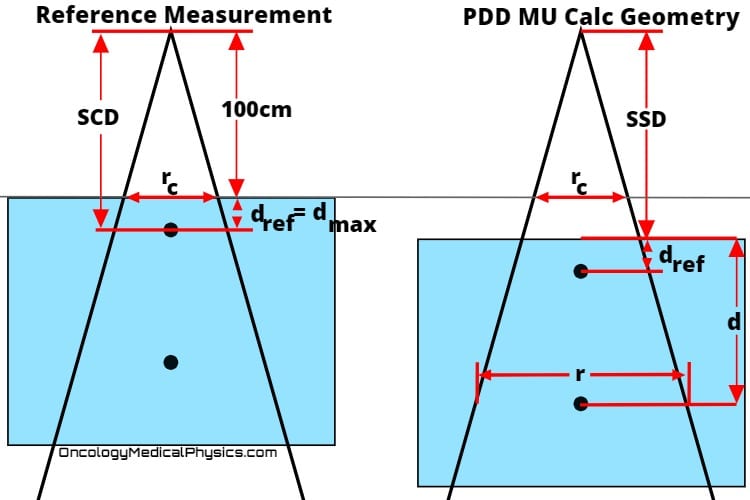
Percent Depth Dose (PDD) is the ratio of dose at a given depth to maximum dose.
PDD is a function of depth, source to surface distance, and field size.to Click here learn more about percent depth dose of photon fields (internal link).
![]()
- SSD is source to surface distance
- d is the depth of interest
- rc is the field size at isocenter
- dmax is the depth of maximum dose
Mayneord F Factor
Mayneord’s F factor the ratio of the inverse square component of percent depth dose (PDD) from the reference souce-to-surface distance (SSD) to another SSD.
![]()
![]()
- SSD1 is the reference SDD
- SSD2 is the adjusted SDD
The F factor is used to convert PDD curves from one SSD to another, for the same depth and collimator setting.
![]()

Key Point: While Mayneord’s Factor is accurate for small shifts, it only accounts for the effect of inverse square law on PDD. A full correction would require addressing changes to phantom scatter and attenuation (air).
Tissue Ratios
Tissue Air Ratio (TAR)
Tissue Air Ratio (TAR) is the ratio of dose at a point in the phantom (Dd) to dose at the same point in free space (Dfs) with full build-up.
- Full buildup in MV photon beams requires large “mini-phantoms.” Because of this, use of TAR in modern clinical calculation is uncommon.
- TAR is approximately independent of distance from source.
![]()

Tissue Phantom Ratio (TPR)
Tissue Phantom Ratio (TPR) is the ratio of dose at a given point and depth in phantom to dose at the same point at the reference depth in phantom.
![]()
")
Tissue Maximum Ratio (TMR)
Tissue Maximum Ratio (TMR) is the ratio of dose at a given point and depth in phantom to dose at the same point at the depth of maximum dose in phantom.
- TMR is a special case of TPR with the reference depth taken as depth of maximum dose.
![]()

Back Scatter Factor
The backscatter factor (BSF) is the ratio of dose at depth of maximum dose in the phantom (Dmax) to dose at the same point in free space (Dfs) with full build-up.
- BSF is a special case of TAR evaluated at depth of maximum dose (dref = dmax).
- BSF is highest for low energies and large field sizes.
![]()
PDD, TAR, TMR, and TPR Conversions
Percent Depth Dose (PDD) and Tissue Ratios such as TPR and TMR are closely related. Although direct measurement is always preferred, it is useful to have an understanding of how to convert between these quantities.
PDD and TMR
![]()
![]()
TMR and TAR
![]()
TMR and TPR
![]()

Scatter Factors
Absorbed dose at a point is a function both of primary and scattered photons. The contribution of scatter to clinical dose calculations depends on both the amount of scatter generated in the treatment head and the amount of scatter generated within the phantom.
Collimator Scatter Factor (Sc) - Output Factor
- Accounts only for scatter arising from treatment head. For this reason the collimator scatter factor is often referred to as the output factor.
- Defined as the ratio of output in air for a given field to that of a reference field.
- Measurement
- No phantom used.
- Best measured using ion chamber with build-up cap large enough to provide full buildup.
- Most commonly measured at isocenter.
Key Point: In MU calculations, Collimator Scatter Fractor should always be taken as the field size at SAD.
Phantom Scatter Factor (Sp)
- Accounts only for scatter arising from the phantom.
- Defined as the ratio of dose rate for a given field size at a reference depth to the dose rate at the same depth using a reference field size with the same collimator opening.
- Measurement
- May be determined for all field sizes by Sp = Sc,p/Sc
- For large field sizes may also be found using phantoms of differing sizes with the same collimator setting. This method is not clinically practical.
Key Point: Phantom scatter factor should always be taken as the field size at the depth of interest.
Total Scatter Factor (Sc,p)
- Accounts for scatter arising from both treatment head and within the phantom.
- Defined as the ratio of dose rate at the reference depth for a given field size to a reference field size at reference depth.
- Measurement
- Measure output for various field sizes in phantom which exceeds dimensions of maximum field size.
Monitor Unit Calculations
Photon Field MU Calculations
![]()
- MU are the number of monitor units to be delivered.
- Rx is the prescription dose at the depth of interest (cGy).
- K is the calibration output factor in units of cGy/MU.
- Usually 1cGy/MU at dmax in 10cm x 10cm field and an SSD of 100cm.
- factor is either PDD or TMR .
- Tissue Maximum Ratio (TMR) provides the simplest method for computing required in an isocentric technique.
- Percent Depth Dose (PDD) is the method of choice for computing the required monitor units for non-isocentric techniques.
- Sc and Sp are the collimator and phantom scatter factors.
- ISC is the inverse square correction.
- For PDD calculations use:

- For TMR calculations use:
- For PDD calculations use:
- TT is the treat to level, taken to be 1 if isodose line is not specified.
- Although many prescriptions will simply define the prescription dose to be the 100% isodose lines, special cases (such as electron treatments and stereotactic radiosurgery) may not.
- For example, a physician may prescribe to the 90% isodose line in which case TT would be taken as 0.9.
- WF is the wedge factor, taken to be 1 if no wedge is used.
- TF is the transmission factor, taken to be 1 if no trays or other devises are placed in the beam path.
- OAF is the off axis factor, taken to be 1 if calculation is made along the central axis.
Electron Field MU Calculations
![]()
- MU are the number of monitor units to be delivered.
- Rx is the prescription dose at the depth of interest (cGy).
- K is the calibration output factor in units of cGy/MU.
- Usually 1cGy/MU at dmax in 10cm x 10cm field and an SSD of 100cm.
- PDD is percent depth dose.
- Note that only PDD is used in electron calculations.
- AF is the applicator factor.
- The applicator factor is the ratio of the the output with the utilized applicator to the output of with the reference applicator size (typically 10cm by 10cm).
- The applicator factor is the ratio of the the output with the utilized applicator to the output of with the reference applicator size (typically 10cm by 10cm).
- CF is the cutout factor.
- The cutout factor is the ratio of output with the cutout placed in the applicator to the output of the applicator with no cutout in place.
- The cutout factor is the ratio of output with the cutout placed in the applicator to the output of the applicator with no cutout in place.
- TT is the treat to level, taken to be 1 if isodose line is not specified.
- Although many prescriptions will simply define the prescription dose to be the 100% isodose lines, special cases (such as electron treatments and stereotactic radiosurgery) may not.
- For example, a physician may prescribe to the 90% isodose line in which case TT would be taken as 0.9.
- ISC is the inverse square correction.
- VSD is the virtual source distance.
- g is the difference between the reference SSD and the setup SSD.
Knowledge Test
Log In to access to the full quiz
Navigation
Not a Member?
Sign up today to get access to hundreds of ABR style practice questions.