
Basic Photon Treatment Planning
Multi-Field Dose Distributions
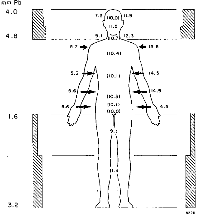
Parallel Opposed Fields
Parallel opposed fields may be used for whole brain, mediastinal and other simple treatment sites.
Features of parallel opposed fields:
- More homogeneous dose distribution than single field
- Lower isodose levels spread laterally while higher isodose levels narrow in center to an "hour glass" shape
- Minimum dose along beam axis is found at phantom mid-line
- Depth of maximum dose increases with increased energy
- Skin sparing increases with increased energy
- Tissue homogeneity increases with increased energy
Tissue lateral effect (TLE) describes the situation in which, for parallel opposed beams, the dose near the surface becomes large relative to the dose at mid-plane for larger patients and for treatments with lower energies.
Energy Selection
Treatment energy selection is usually dictated by the ratio of maximum to minimum dose which is, in turn, determined by the patient's thickness. Generally, a higher energy will be selected if this ratio is greater than 1.1 - 1.15.
One common exception to this are targets embedded in lung where high energy beams (>10MV) require too much build-up to adequately cover the target.


Field Junctions
Some target volumes are too large to be fully covered by a single beam. These targets are often treated with multiple fields. Because both fields have divergence, care must be taken in managing field overlap.
The point of field junction is typically at the point at which the geometric field boundaries (the 50% isodose line for a single field) come into contact.
This is convenient at the geometric field boundary nearly coincides with the light field, making setup simple.
Additionally the summation of the fields at the junction is 50% + 50% = 100%.
Match-at-Depth
The match-at-depth technique is used when two or more parallel fields are incident on a phantom adjacent to one another.
The depth of the match line typically corresponds to the most superficial aspect of the target or, for multiple opposed fields, the phantom/patient midline.
The surface separation (S) of two match-at-depth fields is determined by the source-to-axis distance (SAD) of each field, the field size (L) and the depth of the match line (d).
![]()

Non-Parallel Field Matching
Non-parallel field matching requires collimator and couch rotation to account for divergence of both beams.
Couch rotations are often referred to as couch kicks.
The most commonly cited example of such a beam arrangement is craniospinal fields. In this treatment Posterior-to-Anterior fields are used to irradiate the spine while opposed lateral fields are used to irradiate the whole brain.

Matching the collimator angle of the brain lateral fields to the spinal field divergence is achieved by:
![]()
Matching the opposed lateral brain fields is achieved via a couch kick with an angle determined by:
![]()
Field Modifiers
Wedges
Wedges are devices which adjust the angle of isodose line at a given depth via differential attenuation of the beam.
Wedge Angle is usually defined at 10cm depth in water.
Wedge Transmission Factor is defined as the ratio of the output with the wedge to the output without the wedge.
![]()

Types of Wedges
Physical (Individual) Wedges are made of metal and are attached to the treatment head prior to irradiation. The thin end of the wedge is known as the toe and the thick end is known as the heel.
-
- Physical wedges differentially harden the beam.
- Physical wedges increase surface dose due to increased scatter.
Electronic (Dynamic) Wedges produce the appropriate angle by slowly moving the linac primary collimator or multi-leaf collimator across the field during delivery.
-
- Electronic wedges do not harden the beam or significantly increase scatter (although there may be a small increase due to the effectively smaller field size).
Universal Wedges, such as those found on Elekta machines, house a single 60 degree physical wedge inside the treatment head. Wedge angles of less than 60 degrees may be produced by delivering part of the beam without a wedge (i.e. open field) and the rest using the universal wedge.
Common Wedge Applications

Dual Field Wedges
When two fields intersect at an angle other than 180 degrees, the resulting dose distribution will be heterogeneously weighted toward greatest overlap. Wedges may be used to improve the uniformity of such dose distributions.
The optimal wedge angle is determined by the angle of the incident beams (the hinge angle) as:
![]()
Breast Tangents
Traditional breast plans use two opposed fields positioned tangent to the chest wall. This approach minimizes dose to the heart and lungs. Because the beam path is thickest near the chest wall and becomes thinner superficially, open fields can result in significant dose heterogeneity. Wedges, with the toe toward the chest wall, may be used to produce a more uniform dose distribution.

Blocking
Blocking is used to create fields of different shapes and sizes. The simplest blocking is accomplished using only the jaws located in the treatment head. Jaws, however, are only able to produce a rectangular field.
Custom Cutouts
The first method developed for producing irregular field shapes was the development of custom lead or Cerrobend cutouts and blocks. These blocks are typically mounted to a Lucite plate (tray) which could be affixed to the treatment head.
95% attenuation is considered clinically acceptable for a custom cutout or block.
Cerrobend is a brand name for Lipowitz metal which is used more often than lead to produce custom blocks because its lower melting point makes it easier to work with.
Cerrobend has a lower melting point than lead (70°C vs 327°C).
Cerrobend has a lower density than lead (9.4g/cc vs 11.34g/cc).
![]()

| Beam Quality | Lead Block Thickness | Cerrobend Block Thickness |
|---|---|---|
| Co-60 | 5.0 cm | 6.0 cm |
| 6MV | 6.5 cm | 7.8 cm |
| 10MV | 7.0 cm | 8.4 cm |
| 25MV | 7.0 cm | 8.4 cm |
Multileaf Collimation
The multileaf collimator (MLC) is a device made up of individually controlled leaves used to create complex field shapes.
Because MLC leaves have a finite width, the orientation of the leaves relative to the target is important. Generally, the collimator should be rotated to place the direction of leaf motion parallel to the shortest axis of the target.

Field-in-Field
Field-in-field (FIF) is an advanced field shaping technique utilizing the MLC. FIF is most often used to reduce the intensity of high dose regions by blocking those regions for some fraction of the beam.
Field-in-field is similar to intensity modulated radiation therapy (IMRT) in that it uses the MLC to produce multiple collimator openings with the goal of creating a conformal and uniform dose distribution. Unlike IMRT, which is planned using an inverse planning algorithm, FIF is forward planned.
Steps in Field-in-Field delivery
- The majority (typically 80-90%) of the dose at a given beam angle is delivered with the largest applicable MLC setting.
- The MLC is partially closed to occlude further dose to high dose regions and the remainder of the dose is delivered. This is the field within a field.
- Between 1 and 5 MLC positions are typically used.

Key Point: Forward planning refers to the design of a radiation field by means of a user directly placing the field and calculating the resulting dose distribution. Inverse planning refers to a planning technique in which a user defines a set of end dose distribution goals (i.e. target dose, limiting dose to organs, etc.) and an algorithm attempts to produce a set of fields which achieve these goals.
Tissue Compensators
Bolus
Bolus refers to material placed on the patient’s skin surface with the intent of influencing dose distribution. The term may refer to either compensating bolus or buildup bolus depending upon the intent and construction of the bolus.
Buildup Bolus
Buildup bolus refers to material placed directly on the skin surface with the intent of increasing skin dose.
Buildup bolus is often used in treatment of skin lesions as well as to increase dose around an excision scar, especially in breast cancer treatment.
Buildup bolus is typically of uniform thickness between 5-10mm using superflab. Other materials such as brass may also be used for this purpose.
Compensating Bolus
Compensating bolus refers to material placed directly on the skin surface to even out irregular contours resulting in a more uniform dose distribution.
Compensating bolus is most commonly used in electron therapy where high and uniform superficial dose is desired.
Compensating bolus also reduces skin sparing which is undesirable in many applications. As a result, use of a tissue compensator may be preferred for photon treatments.


Compensating Filters
Compensating filters, commonly referred to as compensators, are attenuating material placed in the beam path to compensate for differences in patient thickness.
Compensators are distinguished from compensating bolus because they are not placed in direct contact with the patient. As a result, compensators allow greater skin sparing than compensating bolus. Additionally, compensating filters are typically used in photon treatments.
Compensator facts
- Compensators are typically made of lead, copper or acrylic.
- Compensators will harden photon beams and increase scatter dose.
- Compensators can have finer resolution than an MLC.
The thickness of compensator material required may be estimated as in the below equation.
![]()
![]()
- t is the thickness of the compensator material.
- μ is the attenuation coefficient of the compensator material.
- TPR is the tissue-phantom ratio at the point of interest.

Navigation
Not a Member?
Sign up today to get access to hundreds of ABR style practice questions.