
Scintillation (Gamma) Camera
Design and Operation
Overview
Scintillation cameras, sometimes referred to as gamma cameras, are scintillation-type detectors which convert radiation to light and, ultimately, to an electric signal which may be read out digitally. The scintillator is coupled to a set of photomultiplier tubes (PMTs) which convert light into electrical signals. These electric signals are then digitally processed to produce an image.
Anger Scintillation Camera Design
The most common scintillation camera design was created by Hal Anger in the 1950s. The Anger camera features a single scintillation crystal coupled to multiple photomultiplier tubes which are able to encode the location of the radiation interaction with the crystal. Other designs, such as the multi-crystal design, are less commonly used.
Scintillation Crystal
The scintillation crystal emits visible or ultraviolet light after interacting with ionizing radiation. High detection efficiency requires a scintillator with the following properties:
- A high conversion factor (>10%) meaning that a large fraction of radiation energy deposited in the scintillator is converted to light.
- A short decay time which limits the delay between irradiation and scintillation.
- Material should be transparent to its own scintillation wavelength to prevent self-attenuation.
- The scintillation wavelength should be readily detectable by the readout device (PMT, photodiode, etc).
- A large attenuation coefficient for the radiation being measured.
NaI(Tl) Scintillation Crystals
Sodium iodine crystals doped with thallium are the most common scintillation crystals used in nuclear medicine.

Advantages of NaI(Tl) Scintillators
- High conversion efficiency (13%)
- High attenuation coefficient for photons in the range of most radiopharmaceuticals (70-365keV)
- Prompt photon emission with a decay constant of 250ns
- High light yield (38 photons/keV is absorbed)
Disadvantages of NaI(Tl) Scintillators
- The attenuation coefficient is too low to efficiently collect the 511 keV annihilation photons produced during PET imaging studies
- The crystal is hydroscopic meaning that it must be enclosed to prevent atmospheric water absorption
- Crystals are fragile and may shatter if struck or subjected to extreme temperature changes
- Susceptible to accumulated radiation damage including that from ultraviolet light (fluorescent lamps and sunlight)
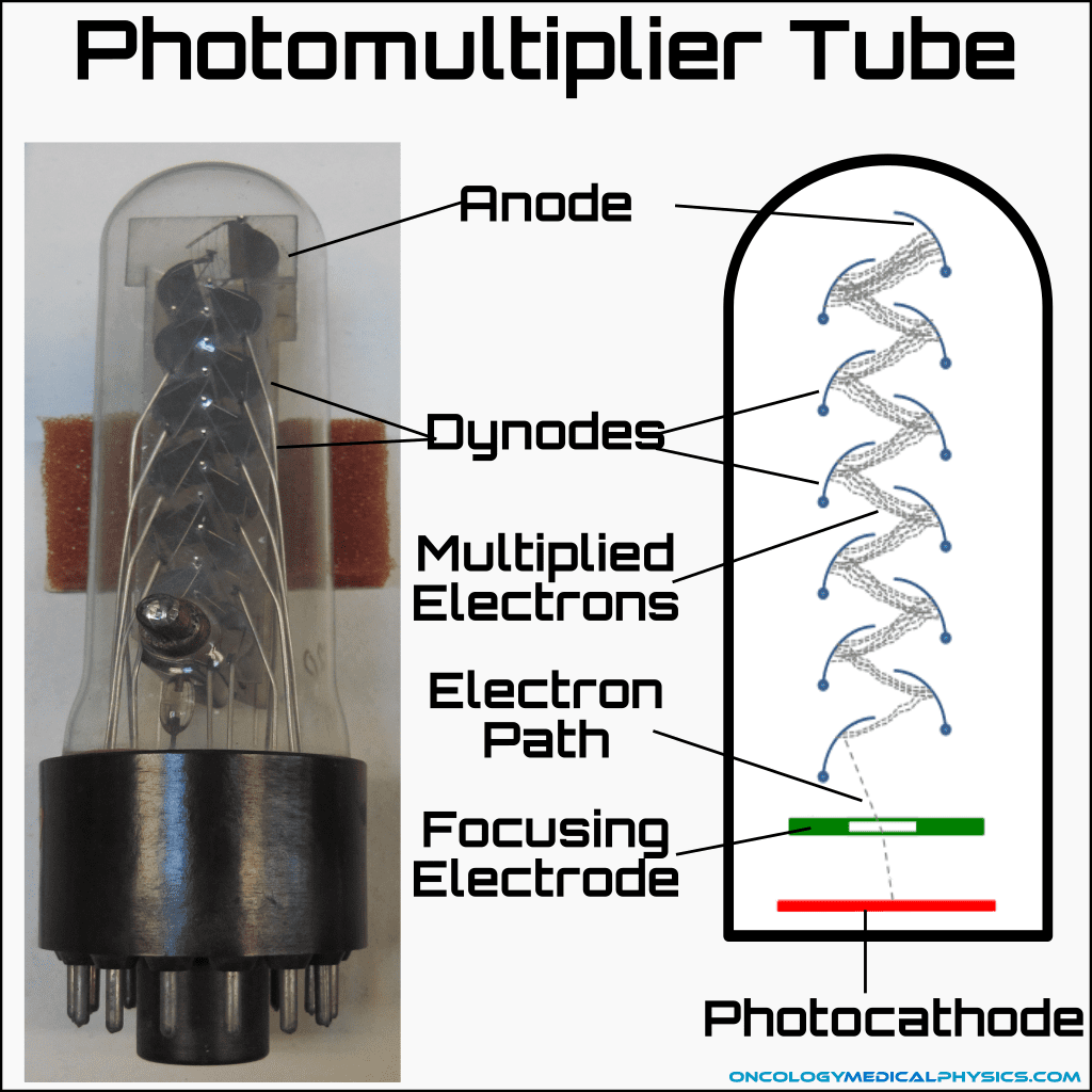
Photomultiplier Tube
Photomultiplier tubes (PMTs) are used to convert scintillation light into electrical signals. The basic PMT design consists of an evacuated tube containing a electrodes referred to as dynodes, and an anode. The photocathode emits a small number of electrons (~1 electron/5eV) when struck by scintillation photons. These electrons are accelerated from dynode to dynode by a voltage of about 100V per dynode pair. This acceleration causes each electron reaching a dynode to emit about 5 additional electrons. That means that a 10 dynode PMT achieves an amplification factor of about 510.
Collimators
Gamma camera collimators are devices used to restrict the angle of incidence of radiation upon a portion of the detector. Collimators must attenuate photons in the kV range, so they are typically constructed of materials with a high atomic number, such as lead. All collimators consist of an aperture, through which radiation enters, and lead walls referred to as septa.
Collimator Designs

Parallel Hole
The most common type of collimator is the parallel hole collimator, which consists of thousands of parallel holes and, most often, thin lead foil septa.

Converging
Converging collimators are used to produce magnified images of larger sites than would be achievable with a pinhole collimator. Magnification increases for objects farther from the collimator, but field-of-view decreases as well.

Diverging
Diverging collimators are not in common use today, but were used in the past to produce minified images. The primary benefit of a diverging collimator is that it is able to expand the field-of-view of a scintillation camera.

Pinhole
Pinhole collimators feature a single aperture approximately 5 mm in diameter. They are able to produce magnified images of small objects and are useful in thyroid uptake imaging.
Image Formation Process
1. Radiopharmaceuticals are administered to the patient and differentially accumulate based on biological activity.
2. Gamma photons are generated by radioactive decay.
Radioactive decay may involve direct emission of a photon, as is the case for Tc-99m, or the photons may be generated by annihilation, as is the case for F-18 used in PET imaging. In the case of therapeutic radiopharmaceuticals, the decay is often via β- with photons emitted as the daughter nuclide returns to ground state.
3. Gamma photons exit the patient and are incident upon the collimator.
The septa of the collimator blocks photons that are not parallel to the hole of the collimator. This focuses the resulting image but also reduces the number of photons reaching the scintillator requiring a higher administered activity.
4. The remaining photons interact with the scintillation crystal, producing scintillation photons.
Conversion from keV energies to visible wavelengths allows for collection in the photomultiplier tube. Each keV of gamma photon energy creates approximately 38 photons (assuming it is a NaI scintillator), which are projected in radially from the site of interaction.
Four types of events may be detected in the scintillation crystal:
- Valid events - generated when an unscattered photon oriented parallel to the collimator septa produces scintillation.
- Septal penetration events - occur when a photon that is not oriented parallel to the collimator septa penetrates a septal wall and produces scintillation.
- Object scatter events - occur when photons are scattered within the body before passing the collimator and producing scintillation.
- Detector scatter events - occur when a photon passes the collimator, but is multiply scattered within the scintillation crystal. Detector scatter appears as multiple coincident low energy events.

5. Scintillation photons are converted to electronic signals by a photomultiplier tube.
The PMT converts scintillation photons into electronic signal and amplifies the signal by a factor of about 510. This step allows for the digital signal processing that follows.
6. An energy discrimination circuit rejects the scattered signals.
Energy discriminators, also referred to as pulse height analyzers, are electronic circuits used to reject scatter counts and coincidence interactions by rejecting counts that fall outside of a narrow energy window. Multiple counts are rejected because they produce too great a signal, while scattered counts are rejected because they create too small a signal. The energy discriminator reduces noise in the final image.

7. A position logic circuit determines the origin location of each signal on an x, y plane. Each localized signal is known as a count.
Many scintillation photons are created at each interaction in the scintillator. These photons spread radially from their source and produce signal in multiple PMTs. The precise location of a scintillation can be determined by interpolating the relative signal intensities and positions of the PMTs. The position of the scintillation between two PMTs can be determined as:


8. An image is formed by accumulation of these localized counts.
The x,y coordinate of each count is recorded and an image is formed by accumulation of these counts.

Clinical Gamma Cameras
Most clinical gamma cameras are either single or dual headed designs. In both cases, the gamma camera is mounted to a gantry which allows the gamma camera’s imaging angle to be adjusted.


Imaging Parameters
Acquisition Modes
Frame Mode
In frame mode, counts are digitized into the appropriate image matrix bin immediately after detection. These counts are accumulated in the image matrix over a given amount of time, building up an image directly.
List Mode
In list mode, individual x,y coordinates of each count are stored along with a time marker. This allows retrospective framing of the data after acquisition.
Frame Rate
Frame rate is the length of time over which counts are accumulated in an image. Framing rate is impacted by the expected counting rate and the purpose of the study. High count rates and dynamic studies (such as cardiac exams) allow for faster frame rates. Cardiac studies may be as short as 0.2 to 0.5 seconds per frame.
Artifacts
Pincushion/Barrel
Appearance: Bowing in or out of straight lines and/or regular repeating distortion lines in a flood field.
Cause: Imperfect mapping of scintillation location within the positional logic system.
Resolution: Perform linearity calibration, correcting for imperfect positional mapping.


Navigation

Not a Member?
Sign up today to get access to hundreds of ABR style practice questions.