
Kilovoltage X-ray Generation
Theory of Operation
- First, a cathode containing a heated filament emits electrons via thermionic emission.
- Next, a high voltage is applied between the cathode and the anode which accelerates the electrons toward toward the anode.
- Finally, kilovoltage x-rays are generated by Bremsstruahlung (aka Braking) radiation when the accelerated electrons interact with the nucleus in the x-ray tube anode/target. A minority of x-ray fluence is produced as characteristic x-rays resultant of ejection of orbital electrons in the anode.
Key Point: Mean energy of a clinical kV photon beam is approximately 1/2 - 2/3 of the maximum energy.
X-ray Spectrum
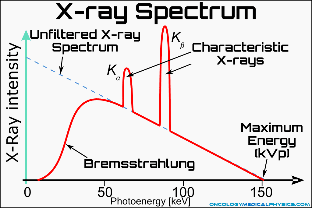
The X-ray spectrum is primarily comprised of Bremsstrahlung produced photons which, in absence of filtering and self-attenuation, would yield a distribution of electron energies that is highest at low energy and decreases approximately linearly to the maximum energy equal to the applied kVp.
- Bremsstrahlung production efficiency is low (<1%) but increases with increased energy.
- Z is the atomic number of the target.
- E is the accelerating potential in volts.
![]()
Filtration
Filtering attenuates the low energy photons more than higher energy photons. This causes the "hump" shape of the fluence energy spectrum.
Characteristic X-rays
Characteristic X-rays are emitted when a photon interacts with the target such that an inner shell (usually k shell) orbital electron is ejected. To fill the orbital vacancy, an outer shell electron descends to the lower energy inner shells by emitting an X-ray. These X-rays are called characteristic X-rays because they are emitted with energies corresponding to the difference between outer shell and inner shell energies.
- Characteristics X-rays cause "spikes" in the X-ray fluence energy spectrum.
![]()

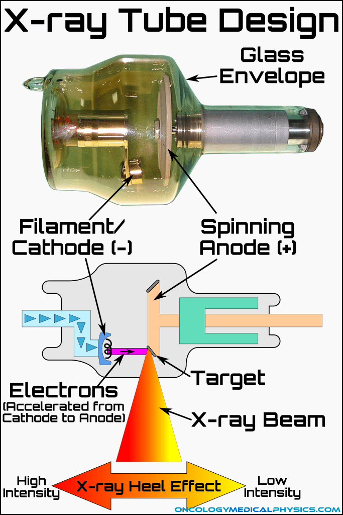
X-ray Tube Design
Anode
- A positively charged anode serves as the target for the accelerated electrons.
- The anode must be made of a high atomic number material in order to achieve reasonable efficiency in Bremsstrauhlung photon production.
- Anode must be able to handle high heat loads because of inefficient Bremsstrahlung production in this energy range (<1% efficiency).
Cathode
- The cathode consists of a wire filament and a negatively charged focusing cup.
- When heated by an applied current, the filament emits a cloud of electrons.
- The focusing cup concentrates the electrons for acceleration which improves penumbra.
Envelope
- Maintains a vacuum within the X-ray tube.
- A vacuum is important to prevent air scattering of the electrons which would increase focal size increase photon beam penumbra.
- Historically, a glass envelope was used to ensure a vacuum within the x-ray tube. Today, many kilovoltage x-ray tubes utilize a metal-ceramic design which offers several benefits which, taken together allow for smaller x-ray tubes that produce kV photons at higher efficiency and requiring less current.
Key Point: Tungsten is a superior target/anode material to lead because of its high melting point (Tungsten: 6192F vs Lead: 612.4F).
Power Generation
Power is supplied to the X-ray tube in the form of a (nearly) constant direct current (DC) voltage. Although U.S. power distribution voltages are in the kV region (110kV and above are standard), the power supplied to buildings is typically 120V or 240V. Further, power is delivered in alternating current (AC). A transformer and a rectifier are required to convert the VAC outlet power to kVDC power.
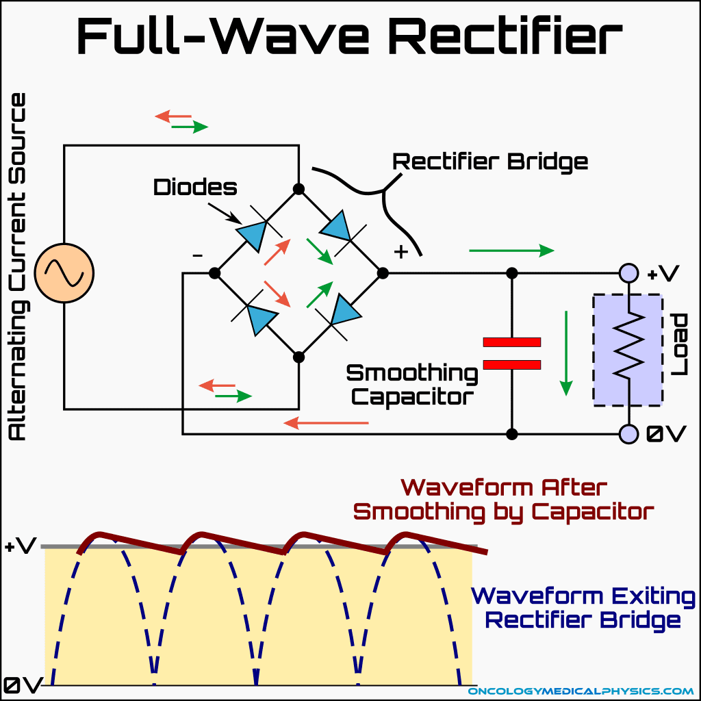
Rectifiers
A full-wave rectifier is used to convert alternating current (AC) to direct current (DC) for use in X-ray generation. A rectifier bridge is formed by connecting four diodes, each of which allows current to flow in only one direction. The rectifier bridge inverts the negative portion of the AC waveform creating a waveform that oscillates between the maximum voltage and 0. A smoothing capacitor is then used to convert the waveform exiting the rectifier bridge into an approximately DC source.
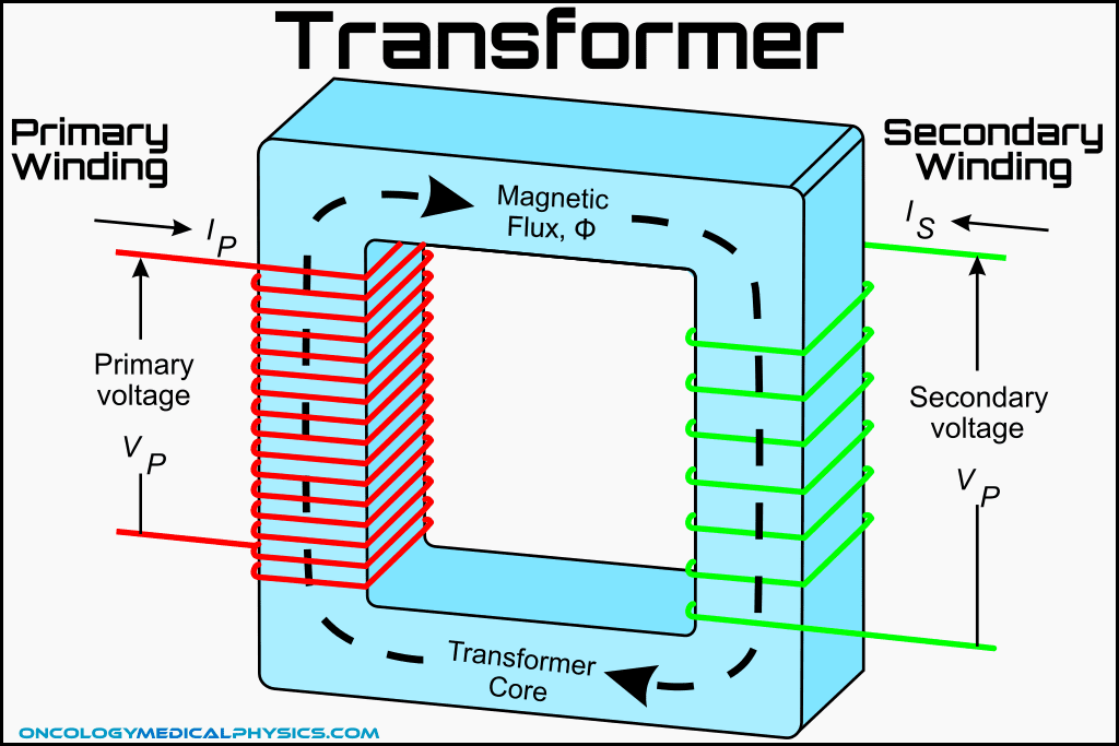
Transformers
Transformers use electromagnetic induction to transfer energy from one wire to another. In a transformer, a wire supplying power (known as the primary winding) is wrapped around a metallic transformer core. A second wire is wound around the transformer core and is induced to transmit power. By varying the ratio of the number of winding of the primary winding to the secondary winding, the voltage may either be increased (a step-up transformer), decreased (a step-down transformer), or remain unchanged (an isolation transformer).
Transformer law: The ratio of the voltages between the secondary winding (Vs) and the primary winding (Vp) is equal to the ratio of the number of turns in the secondary winding (Ns) to the number of turns in the primary winding (Np).
![]()
Heat Management
Heat is a major concern in X-ray tube design because of the low efficiency of X-ray production. Heat dissipation is accomplished with the following features:
- High melting point anode materials:
- Despite being a lower Z (i.e. lower efficiency) material, tungsten is favored over lead because of its high melting point.
- Rotating anode:
- The anode rotates during X-ray production which spreads out the heat over a larger area.
- Rotations speeds range from 3,000 rpm to 10,000 rpm!
- Oil heat dissipation:
- Heat collected in the anode is radiated and conducted out to an oil bath surrounding the tube.
- Oil coolant is favored over water-based coolant because it is not corrosive and acts as an electrical insulator.
Factors Impacting Photon Fluence
kVp
Kilovoltage peak (or peak kilovoltage) is the maximum voltage across the X-ray tube. Because voltage across the tube is not constant, kVp is higher than mean kV.
mA/mAs
Tube current (mA) is the electron flow (i.e. number of electrons per second) from cathode to anode within an X-ray tube. Tube current is related to electric power as in the below equation:
![]()
mAs is the product of tube current (mA) and time in seconds (s). mAs is related to electric energy as in the below equation:
![]()
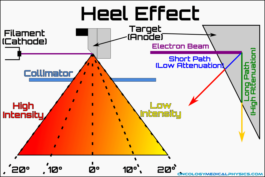
Heel Effect
Heel effect is the reduction in X-ray beam intensity toward the anode side of an X-ray field. Heel effect is caused by greater attenuation of X-rays inside the anode.
Knowledge Test
This is the sample version of the full quiz. Log in or register to gain access to the full quiz.
Navigation
Not a Member?
Sign up today to get access to hundreds of ABR style practice questions.