
Total Body Irradiation
Overview
Total Body Irradiation (TBI) involves giving a high uniform dose to the whole body using photon fields and is the subject of AAPM Task Group 29. TBI is most commonly prescribed as preparation for hematopoietic cell transplant (HCT) commonly referred to as bone marrow or stem cell transplant. TBI improves HCT by suppression of the immune system, thereby reducing the likelihood of Graft Versus Host Disease. TBI is also able to eradicate the malignant hematopoietic cells or those effected by genetic disorders.
Downloads
AAPM TG-29: The Physical Aspects of Total and Half Body Irradiation (External link)
Treatment Technique
Common Prescriptions
Prescriptions are commonly specified as a dose to a point (typically patient center at level of umbilicus).
- Dose limits to other locations specified explicitly.
- Specify dose rate, especially for single and hypofractionated schemes.
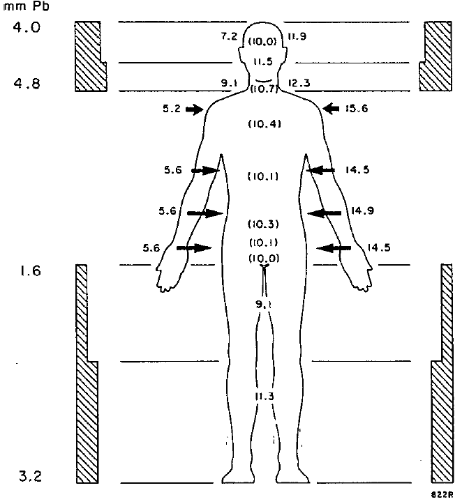
- Clinical dose uniformity of ±10% at mid-line is acceptable.
Low Dose TBI
Prescription: 2Gy in single fraction
Intent: Cytoreduction
Associated Diseases
- Eliminating malignant cells
- Leukemias
- Lymphomas
- Eliminating cells with genetic disorders
- Fanconi’s Anemia
- Thalessemia Major
High Dose TBI
Prescription:
- 4-10Gy in single fraction
- 10-14Gy in 8 fractions
- Typically delivered BID (twice daily)
Intent: Immunosuppression
Killing lymphocytes and destroy bone marrow reduces graft rejection in bone marrow transplant.
Associated Diseases: Aplastic Anemia
Patient Positioning
- Anterior-Posterior treatments allow better uniformity and ease of lung sparing.
- May be treated in standing position with support or decubitus (lying on side).
- Lateral field treatments with patient lying down more comfortable and require less specialized immobilization.
- Compensators will typically be used for the head and ankles.


Potential Clinical Complications
- Lung toxicity is a major concern with high dose TBI. This is the reason for reduced dose rate and lung blocking.
- Nausea, vomiting, and diarrhea are expected.
- Interstitial pneumanitis is a potentially lethal side effect the risk of which may be greatly reduced by fractionation.
Key Point: TBI involves delivering a potentially fatal dose of radiation. Even low dose TBI of 2Gy whole body dose is sufficient to induce Hematopoietic Syndrome while high dose TBI is sufficient to induce Gastrointestinal Syndrome.
Accelerator Settings
- Dose rates kept low (5-10cGy/minute at depth of maximum dose).
- This reduces normal tissue toxicity especially for the lungs.
- Low dose rate becomes less critical for highly fractionated regimens.
- Energy: 10-18MV
- Higher energy reduces Tissue Lateral Effect thereby improving uniformity.
- Higher energy also reduces skin dose which may be undesirable.
- An extended SSD is typically used
- This improves homogeneity by reducing impact of inverse square law on percent depth dose.
- Gantry is positioned at 90 degree to produce a horizontal field.
- Collimator rotation (typically 45 degrees) may be needed to accommodate patient geometry.

Scatter Plate
An acrylic scattering plate, sometimes referred to as a spoiler, may be placed in front of the patient to increase skin dose. This is especially valuable for treatments using very high photon energy.
Compensators
Compensating filters, commonly referred to as compensators, are attenuating material places in the beam path to compensate for differences in patient thickness.
Compensators are distinguished from compensating bolus because they are not placed in direct contact with the patient. As a result, compensators allow greater skin sparing than compensating bolus. Additionally, compensating filters are typically used in photon treatments.
Compensator facts
- Compensators are typically made of lead, copper, or acrylic.
- Compensators will harden photon beams and increase scatter dose.
- Compensators can have finer resolution than an MLC.
The thickness of compensator material required may be estimated as in the below equation.
![]()
- t is the thickness of the compensator material.
- μ is the attenuation coefficient of the compensator material.
- TPR is the tissue-phantom ratio at the point of interest.
Key Point: The attenuation coefficient of a compensator used in TBI’s large field geometry will be different than the attenuation coefficient taken in standard narrow field geometry. Therefore, attenuation coefficients should be measured in the TBI setup.
Dosimetry
Monitor Unit Calculations
Either percent depth dose (PDD) or tissue maximum ratio (TMR) may be used to compute monitor units.
- MU is the number of monitor units delivered per beam for parallel opposed TBI treatments.
- The 2 in the denominator divides up the total MU between each beam.
- O is the output factor. Unit: cGy/MU
- Sc is the collimator scatter factor.
- Sc, should be based on the jaw opening.
- Sp is the phantom scatter factor.
- Sp, should be based on the phantom size which may be determined by measuring the dimensions of the patient’s thorax.
- SCD is the source-to-calibration distance (i.e. the distance from the source to the point where the output factor was measured).
- SMD is the source-to-midline distance (i.e. the distance from the source to the midline of the patient under TBI treatment).
![]()
Key Point: Output and scatter correction factors should ideally be measured using TBI geometry (i.e. at extended treatment distance) but may also be calculated from nominal beam data (i.e. at 100cm SCD). It has been shown that calculations based on nominal beam data vary by less than 1.5% from calculations based on beam data generated in TBI geometry. .
Dose Monitoring
Dose monitoring is necessary to ensure proper prescriptive dosing. TLDs, OSLDs, or diode detectors are appropriate for treatment dose monitoring. Port films may also be used to assure alignment of compensators and blocks.
- Entrance and exit dosimeter pairs may be used to determine dose to mid-line
- May either take simple mean or, preferably, apply the known depth dose curve to determine mid-line dose.
- Placing dosimeters along mid-line is preferred when possible
- E.g. In mouth, between legs
Navigation
Not a Member?
Sign up today to get access to hundreds of ABR style practice questions.