Ultrasound System Design and Operation
Quick Reference
- dB = 10log(I/I0)
- Speed of sound in soft tissue = 1540 m/s
- Speed of ultrasound in bone = 4080 m/s
- Attenuation rate in tissue = 0.5 dB/cm/MHz
- Higher frequency => higher attenuation
- Typical ultrasound frequencies are around 1-20 MHz
- Typical ultrasound pressure is about 1 MPa (about 10 times the atmospheric pressure)
Basic Operation
Ultrasound imaging uses high frequency sound waves to produce images of anatomical structures. Image formation is a four-step process:
- The transducer emits an ultrasound beam which travels through the body.
- The ultrasound beam encounters an interface between tissues of different acoustic impedance, which causes some of the ultrasound energy to be reflected back to the transducer.
- The transducer detects the reflected ultrasound energy.
- A computer uses the time between beam emission and reflection detection to determine the distance to the reflecting object. It produces an image based on the distance to reflection and the intensity of the reflection.
Transducers
Ultrasound transducers are responsible for the production and detection of ultrasound waves. There are a variety of transducer designs optimized for a variety of imaging tasks. All designs include the basic components of a piezoelectric element, a damping block and a matching layer.
Piezoelectric Element
The piezoelectric element (often referred to as the element or crystal) is responsible for both generating and detecting ultrasound waves. When an electrical signal is applied to the piezoelectric material, the crystal mechanically deforms. This deformation is used to create the ultrasound wave. Conversely when a sonic wave returns to the piezoelectric material, it mechanically deforms the crystal again and generates a detectable electronic signal.
Transducer Materials
Lead-zirconate-titanate (PZT) is the most common piezoelectric material used in ultrasound transducers.
Transducer Resonance and Thickness
The effectiveness of a piezoelectric material at producing and detecting ultrasound waves is greatly enhanced for wavelengths in multiples of ½ of the material thickness. For these wavelengths, the material is able to resonate at its natural frequency, which amplifies the signal. Resonant medical transducers are designed to resonate at a target ultrasound frequency.
Ring Down
Ring down is the vibration in the piezoelectric element which continues after the electronic signal has ended. A long ring down time leads to lower bandwidth (a smaller range of produced frequencies), but also increases the spatial pulse length (SPL), which negatively impacts axial resolution.
Damping Block
The damping block absorbs the backward directed ultrasound energy and reduces ring down time. As previously noted, reduced ring down time will improve spatial pulse length (SPL) at the cost of increased bandwidth.
The Q-Factor
The Q-factor is the ratio of the center frequency (f0) to the bandwidth.
A high Q-factor transducer indicates a narrow bandwidth and a long SPL. “High Q” transducers are commonly used in Doppler ultrasound application, where a narrow bandwidth is needed to accurately quantify flow rate.
A low Q-factor transducer indicates a broad bandwidth and a short SPL. Most imaging applications use a “low Q” transducer, which has the short SPL needed for high spatial resolution along the beam axis.
Key Point: A “Low Q” transducer does not indicate poor imaging quality! In fact, many imaging applications use “low Q” transducers to optimize spatial resolution along the beam axis.
Matching Layer
The matching layer provides the interface between the piezoelectric element and the surface of the patient. Matching layers have an acoustic impedance that is between the acoustic impedance of the element and that of the patient’s surface. This bridging of the impedance gap improves the efficiency of acoustic energy transmission from the transducer to the patient and back again by reducing the amount of energy reflected at the interface. Matching layers typically have a thickness of ¼ the operating wavelength of the transducer.
Resonant and Multi-Frequency Transducers
Resonant frequency transducers are very efficient at producing and detecting a narrow bandwidth of ultrasound frequencies. Resonant frequency transducers use a piezoelectric element with a thickness of ½ the desired ultrasound wavelength.
Multi-frequency transducers are designed to efficiently produce and detect a large bandwidth (range of frequencies). They consist of a piezoelectric material which is manufactured in such a way as to produce small rods on one surface. This surface is then coated with epoxy to create a flat face. An additional benefit of multi-frequency elements is that their acoustic properties are closer to that of soft tissue than standard PZT (lead-zirconate-titanate) elements, which improves acoustic transmission.
Transducer Arrays
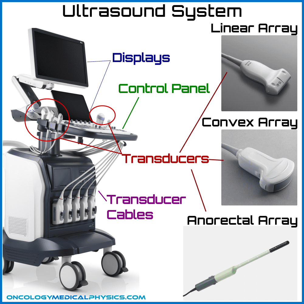
Most ultrasound systems use transducers consisting of 128 to 512 rectangular elements organized in an array. These arrays allow imaging over a large area while maintaining high lateral spatial resolution. There are two common types of arrays which are defined by their mode of operation; linear and phased.
Linear Arrays
In linear arrays, only a small group of elements are used to produce ultrasound waves, but the whole array is used to detect returning echoes. By varying the number of elements producing sound, the user can change the width of the ultrasound beam. Linear arrays may be either flat or curved (also referred to as “curvilinear”.)
Phased Arrays
Phased arrays fire all elements of the transducer in rapid succession which allows these arrays to be steered electronically. Electronic beam steering allows a transducer to scan over an area without the user having to physically move the transducer.
The Ultrasound Beam
After leaving the transducer, the ultrasound beam first converges then diverges. The converging portion of the ultrasound beam is known as the near field, while the diverging portion is called the far field.
Near Field
The near field, also called the Freznel zone, converges because of wave interference at the periphery of the beam. This interference also causes complex variations in acoustic pressure amplitude within this region. The length of the near field is dependent on the radius of the transducer and on the ultrasound wavelength.

Far Field
The far field, also called the Fraunhofer zone, is the diverging region of the acoustic beam. In the far field, the acoustic pressure intensity decreases continually. The angle of beam divergence is again determined by the radius of the transducer and the ultrasound wavelength.
Side and Grating Lobes
Side lobes and grating lobes are unwanted ultrasound energy emitted laterally to the main beam. Side lobes are caused by the radial expansion of the transducer and grating lobes are a consequence of a non-continuous transducer surface composed of discrete elements. The misdirected energy of side and grating lobes can cause false echoes to be recorded, resulting in imaging artifacts.
Ultrasound Imaging Modes
Echo Display Modes
A-Mode (Amplitude)
A-mode displays echo amplitude as a function of distance. It was historically used to determine the distance to objects of different intensities, such as brain tumors. Today, A-mode has limited use because it does not produce a readily understood image. It is primarily used in ophthalmology distance measurements.
B-Mode (Brightness)
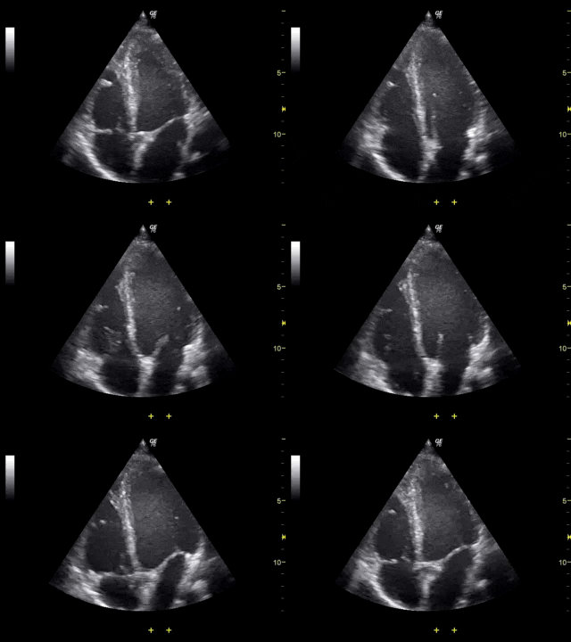
B-mode converts echo amplitude into grey scale to produce an image and is what most people think of when they think about ultrasound imaging. B-mode produces 2D images of underlying anatomy in near real time.
M-Mode (Motion)
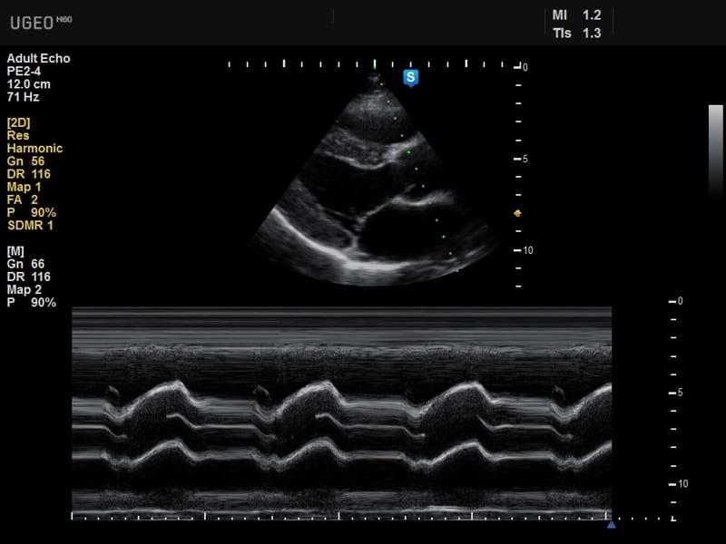
M-mode uses the grey scale information produced in B-mode to produce a graph of object motion over time. M-mode is commonly used in cardiac imaging to assess the function of the myocardium and valve leaflets. M-mode imaging in cardiology is often combined with Doppler imaging to assess blood flow within the heart.
Doppler Mode
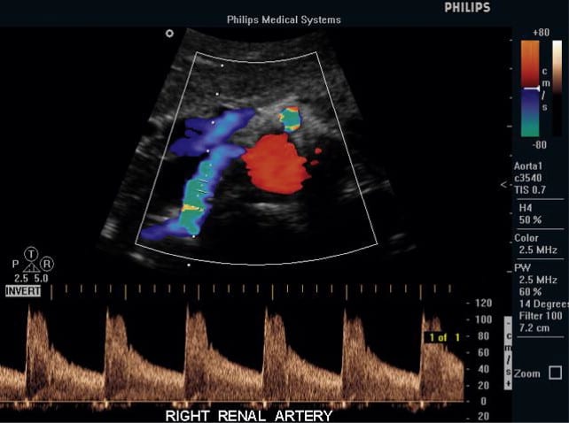
Doppler display mode images fluid motion using the Doppler shift induced by moving reflectors, such as blood cells. The velocity of flow can be determined as follows:
- vflow is the fluid flow velocity
- fi is the emitted frequency
- fd is the Doppler shifted frequency
- θ is the angle between the direction of wave propagation and fluid flow
Navigation
Not a Premium Member?
Sign up today to get access to hundreds of ABR style practice questions.


