
CT Artifacts
The term Artifact refers to any systematic discrepancy between the CT numbers in the reconstructed image and the true attenuation coefficients of the object. CT artifacts are generally divided into three categories: Physics-Based Artifacts, Patient-Based Artifacts, and Scanner-Based Artifacts.
Physics-Based Artifacts: Artifacts which arise from the physical processes involved in image acquisition. Examples include beam hardening artifact, partial volume artifact, projection/view aliasing, photon starvation artifact and cone beam artifact.
Patient-Based Artifacts: Artifacts caused by factors related to the patient during the scan. Examples include motion artifact and metal artifact.
Scanner-Based Artifacts: Artifacts resulting from imperfections in the scanner’s function. Examples include ring artifact and wobble artifact.
Physics Based Artifacts
Beam Hardening
The X-ray beam is composed of a spectrum of energies. As the beam passes through an object, the beam hardens (i.e. becomes more high energy dominant). This results in two effects: cupping and streaking, both of which are physics-based artifacts.
- Cupping: CT numbers obtained in the center of the object are lower than at the periphery.
- Streaking Artifact: Appearance of dark bands or streaks between dense objects in the image.


Photon Starvation (Noise)
Photon starvation is a physics-based artifact that results from an insufficient number of photons reaching the detector. As a result, statistical variation in photon count becomes a dominant source of contrast in the image. This results in an image with streaks along high attenuation beam paths such as those intersecting metal objects or those passing through significant volumes of bone.
Photon starvation may be resolved by increasing mAs or through the use of iterative reconstruction techniques.

Scanner Based Artifacts
Partial Volume Artifact
Partial volume artifact is the averaging of CT number over the volume of the voxel. For example, a voxel which samples a bone (CT number = 800HU) and lung (CT number = -800) would display a CT number of 0 which is representative of water. Because voxel size impacts volume averaging, its effect may be reduced by decreasing field-of-view and by decreasing slice thickness.


Projection/View Aliasing (Undersampling)
Projection aliasing results from the use of too few projections in image reconstruction resulting in aliasing of high frequency objects. The artifact appears as regular streaks projecting from hard, high-contrast edges within the image. This artifact is typically resolved in software by increasing the imager sampling frequency.
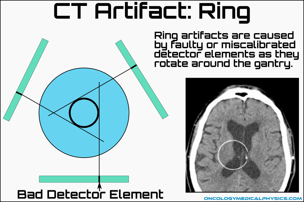
Ring Artifact
When one of the detectors is out of calibration in a rotating detector scanner, the detector will induce a systematic error at its position for each projection. Upon reconstruction, this results in a ring being superimposed on the image. Ring artifact can typically be repaired by recalibration of the detector array or by turning off the faulty detect element.
Cone Beam Artifact
As the number of slices acquired per rotation increases, the beam becomes cone-shaped rather than fan shaped. Beam divergence of this wide cone can cause under sampling (collecting data at too few angles) for objects which are far from the central axis of the scanner. This fundamental undersampling is the cause of cone beam artifact which appears as irregular deformation of the object. Cone beam artifact can be reduced by decreasing pitch or otherwise increasing sampling.
Be aware, several online resources list this problem as similar to volume averaging as a result of a larger volume being collected near the periphery of the detector array. This interpretation is incorrect as can be seen by noting: 1) all detector elements are commonly the same size; and 2) beam divergence means that, although path length is greater, the cross-sectional area sampled is actually smaller for objects sampled with the edge row of the detector. Further, this explanation is not supported by Bushberg et al. (Bushberg, J. T., Seibert, J. A., Leidholt, E. M., & Boone, J. M. (2012). The essential physics of medical imaging. Philadelphia, PA: Wolters Kluwer / Lippincott Williams & Wilkins.)


Patient Based Artifacts
Metal Artifact
The presence of metal in the field of view is beyond the normal range of densities handled by the scanner. This results in severe streaking artifacts projecting from the metal. Additionally, metal can saturate the scanner resulting in a display CT number equal to the scanner's maximum (often +1024). This may result in lead (z=82) being mapped to the same CT number as high-density bone (zeff = 13.8) despite being significantly more attenuating.
Metal artifact can be reduced by increasing kVp with megavoltage CTs (MVCT) yielding a significant reduction in artifact. Additionally, several commercial reconstruction algorithms are available for metal artifact reduction.


Motion Artifact
Patient motion during a scan can result in misregistration of the ray data. This usually appears as directional shading or streaking in the reconstructed image. Motion artifact may be reduced by improved patient immobilization, patient coaching or increased scan speed.
Navigation
Not a Member?
Sign up today to get access to hundreds of ABR style practice questions.